About this Blog

This is my first blog. Ever.

It is simply going to be about my hobby; playing with computer programming. I do not know much about blogging, but I will use this one to learn a bit more about it.

Programming has always been a bit of a passion for me, as from those early days when I first tapped in a sample BASIC program on my old Sinclair Spectrum back in 1986. I have been through many platforms, languages and OS's since, but always carried the hobby with me. I am not particularly good at it; perfection requires a large time investment and continuous practice. I do not have the luxury of the amount of time required to keep the fire burning constantly, so the hobby has inevitably gone through periods of extreme withering. I have, however, finally settled for C++, as the title of this blog implies, and play around with it for some entertainment when ever I can.

This here will serve me as a written record of what I am up to, and hopefully be a reinforcement to my memory every now and then. That is all there is to it.

So, if you read this blog, please don't expect anything snazzy, but be you welcome just the same!

Saturday, 21 January 2012

3D object rotation

So, what was all that business about concatenating matrices in my previous post? Well, it is one of the vital steps in accomplishing the rotation of a 3D shape on a screen. Now that it is clear how to concatenate matrices, I am going to look at what actually goes into those matrices, and what they mean, in 3D graphics. Now, there are all sorts of discussions around the web concerning right hand and left hand coordinate systems. I am not bothered by them. Here's a link that delves a little into that subject, quite coherently. I am just going "right handed", and be done.

When dealing with this subject of 3D rotation, basically, there are these steps to keep in mind;

1. Make three (3x3) matrices, one for each axis, X, Y, and Z, and another one for the concatenation result. It is also a good idea to establish the angle variables for each matrix, too.

2. Make a function that calculates the operations in the matrices (basic trigonometry stuff).

3. Make a function that concatenates the three matrices into one.

4. Make a function that computes where the vertices of the shape are going to end up, applying the final, concatenated matrix.

5. Make a function that draws the shape to the screen.

Steps one and three have already been covered, in part, in my previous post. Step five has also previously been brushed upon in this other previous post. They will have their applicable review here, however.

I make a globally declared float matrix type, 3x3, this way;

typedef matrix[3][3];


...and define my matrices in main() this way;

// the matrices...
matrix X_Matrix, Y_Matrix, Z_Matrix, Final_Matrix;

// the angles for each of the three axis matrices...
float x_angle = 0.0f;
float y_angle = 0.0f;
float z_angle = 0.0f;


These will be in degrees, but C++ math.h trig functions use radians. I do like making my own little function for the conversion. Here it is (again)...

float deg_to_rad(float deg)
{
return deg * ((float)M_PI / 180.0f);
}


...and that is the end of Step One!
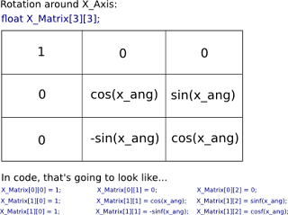
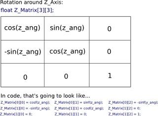
Now, for Step Two, here are the "formats" of my three matrices, X, Y and Z, respectively...


These are the operations that are going to be carried out in each matrix, with its respective angle fed to it. Here's the function that does it...

void Matrix_Handler(matrix X_Mat, matrix Y_Mat, matrix Z_Mat, float x_ang, float y_ang, float z_ang)
{
// X Axis Matrix;
X_Mat[0][0] = 1.0f;
X_Mat[0][1] = 0.0f;
X_Mat[0][2] = 0.0f;

X_Mat[1][0] = 0.0f;
X_Mat[1][1] = cosf(x_ang);
X_Mat[1][2] = sinf(x_ang);

X_Mat[2][0] = 0.0f;
X_Mat[2][1] = -sinf(x_ang);
X_Mat[2][2] = cosf(x_ang);

// Y Axis Matrix
Y_Mat[0][0] = cosf(y_ang);
Y_Mat[0][1] = 0.0f;
Y_Mat[0][2] = -sinf(y_ang);

Y_Mat[1][0] = 0.0f;
Y_Mat[1][1] = 1.0f;
Y_Mat[1][2] = 0.0f;

Y_Mat[2][0] = sinf(y_ang);
Y_Mat[2][1] = 0.0f;
Y_Mat[2][2] = cosf(y_ang);

// Z Axis Matrix
Z_Mat[0][0] = cosf(z_ang);
Z_Mat[0][1] = sinf(z_ang);
Z_Mat[0][2] = 0.0f;

Z_Mat[1][0] = -sinf(z_ang);
Z_Mat[1][1] = cosf(z_ang);
Z_Mat[1][2] = 0;

Z_Mat[2][0] = 0.0f;
Z_Mat[2][1] = 0.0f;
Z_Mat[2][2] = 1.0f;
}


...a bit of overkill, for clarity. It can be seen that, if I preset the matrix "cells" that do not contain any cosf(), sinf() or -sinf() operations at the beginning, this function could easily look like;

void Matrix_Handler(matrix X_Mat, matrix Y_Mat, matrix Z_Mat, float x_ang, float y_ang, float z_ang)
{
// X Axis Matrix;
X_Mat[1][1] = cosf(x_ang);
X_Mat[1][2] = sinf(x_ang);

X_Mat[2][1] = -sinf(x_ang);
X_Mat[2][2] = cosf(x_ang);

// Y Axis Matrix
Y_Mat[0][0] = cosf(y_ang);
Y_Mat[0][2] = -sinf(y_ang);

Y_Mat[2][0] = sinf(y_ang);
Y_Mat[2][2] = cosf(y_ang);

// Z Axis Matrix
Z_Mat[0][0] = cosf(z_ang);
Z_Mat[0][1] = sinf(z_ang);

Z_Mat[1][0] = -sinf(z_ang);
Z_Mat[1][1] = cosf(z_ang);
}


...as all the other cells are always going to be either a zero or a one, according to the format of the concerned matrix. But that is all aside the point. This is all there is, really, to Step Two, so I will press on.

Step Three is the multiplication of these matrices. Do I need to go into this again, seeing as it is already covered? Here's the functions, anyway...

void mult_matrix(matrix Fst_Mat, matrix Sec_Mat, matrix Result_Mat)
{
float temp = 0.0f;
int a, b, c;

for(a = 0; a < 3; a++)
{
for(b = 0; b < 3; b++)
{
for(c = 0; c < 3; c++)
{
temp += Fst_Mat[b][c] * Sec_Mat[c][a];
}
Result_Mat[b][a] = temp;
temp = 0.0f;
}
}
}

// *********************************

void Concatenate_Matrices(matrix First_Mat, matrix Second_Mat, matrix Third_Mat, matrix Fin_Mat)
{
matrix Concat_Mat;

mult_matrix(First_Mat, Second_Mat, Concat_Mat);
mult_matrix(Concat_Mat, Third_Mat, Fin_Mat);
}


The next Step, Four, is the first one that actually comes into contact with vertices or the "stored", 3D object. So, to be clear, here is the object. Yes, it is the everlasting cube. Look at the complete source code at the end of this post to see how it actually fits in.

// a structure to hold the coordinates of the vertex...
struct verts
{
float vx;
float vy;
float vz;
};

// *********************************

// a structure for the order of the drawing of the lines...
struct lines
{
int start;
int end;
};

//.....

// set the positions of the vertices (this is called from main(), with an array of type verts)...
void set_shape_verts(verts *_cube_verts)
{
_cube_verts[0].vx = -100.0f;
_cube_verts[0].vy = -100.0f;
_cube_verts[0].vz = 100.0f;

_cube_verts[1].vx = -100.0f;
_cube_verts[1].vy = -100.0f;
_cube_verts[1].vz = -100.0f;

_cube_verts[2].vx = 100.0f;
_cube_verts[2].vy = -100.0f;
_cube_verts[2].vz = -100.0f;

_cube_verts[3].vx = 100.0f;
_cube_verts[3].vy = -100.0f;
_cube_verts[3].vz = 100.0f;

_cube_verts[4].vx = -100.0f;
_cube_verts[4].vy = 100.0f;
_cube_verts[4].vz = 100.0f;

_cube_verts[5].vx = 100.0f;
_cube_verts[5].vy = 100.0f;
_cube_verts[5].vz = 100.0f;

_cube_verts[6].vx = 100.0f;
_cube_verts[6].vy = 100.0f;
_cube_verts[6].vz = -100.0f;

_cube_verts[7].vx = -100.0f;
_cube_verts[7].vy = 100.0f;
_cube_verts[7].vz = -100.0f;
}

// *********************************

// set which vertices are going to be connected by lines (this is called from main(), with an array of type lines)...
void set_shape_lines(lines *_cube_lines)
{
_cube_lines[0].start = 0;
_cube_lines[0].end = 1;

_cube_lines[1].start = 1;
_cube_lines[1].end = 2;

_cube_lines[2].start = 2;
_cube_lines[2].end = 3;

_cube_lines[3].start = 3;
_cube_lines[3].end = 0;

_cube_lines[4].start = 4;
_cube_lines[4].end = 5;

_cube_lines[5].start = 5;
_cube_lines[5].end = 6;

_cube_lines[6].start = 6;
_cube_lines[6].end = 7;

_cube_lines[7].start = 7;
_cube_lines[7].end = 4;

_cube_lines[8].start = 0;
_cube_lines[8].end = 4;

_cube_lines[9].start = 1;
_cube_lines[9].end = 7;

_cube_lines[10].start = 2;
_cube_lines[10].end = 6;

_cube_lines[11].start = 3;
_cube_lines[11].end = 5;
}


...and here is the function that sets the "rotated" position of those vertices.

void Calc_Screen_Verts(matrix Fin_Mat, ver ts *c_verts, verts *s_verts)
{
float new_x;
float new_y;
float new_z;

float x_center = (float)SCREEN_X / 2.0f;
float y_center = (float)SCREEN_Y / 2.0f;

int i;

for(i = 0; i < CUBE_VERTS; i++)
{
new_x = (Fin_Mat[0][0] * c_verts[i].vx) + (Fin_Mat[0][1] * c_verts[i].vy) + (Fin_Mat[0][2] * c_verts[i].vz);
new_y = (Fin_Mat[1][0] * c_verts[i].vx) + (Fin_Mat[1][1] * c_verts[i].vy) + (Fin_Mat[1][2] * c_verts[i].vz);
new_z = (Fin_Mat[2][0] * c_verts[i].vx) + (Fin_Mat[2][1] * c_verts[i].vy) + (Fin_Mat[2][2] * c_verts[i].vz);

s_verts[i].vx = new_x + x_center;
s_verts[i].vy = new_y + y_center;
s_verts[i].vz = new_z;
}
}


Note that another vert structure is passed to this function (s_verts). This is to receive the output of the rotated vertices held in c_verts. I do not actually want to alter the "mother" vertices of the cube, so I pass them through this function, modify (rotate) them using the concatenated Final_Matrix, and collect the rotation result in s_verts. There is no need to pass any angles, that has already been catered for by the matrix operation done previously. We need only pass the pre-rotated matrix to the function, and with the following operation, plot the new points positions...

Finally, Step Five uses a technique I already covered (again, here) to draw lines on the screen between the vertices held in the lines type structure array. Here it is...

void Draw_Shape(verts *s_verts, lines *c_lines)
{
int i;
for(i = 0; i < CUBE_LINES; i++)
{
al_draw_line(s_verts[c_lines[i].start].vx, s_verts[c_lines[i].start].vy,
s_verts[c_lines[i].end].vx, s_verts[c_lines[i].end].vy,
al_map_rgb(0,255,50), 0);
}
}


Obviously, I have missed out a great deal about perspective calculations, or vertex sorting for depth. That was not the point of these posts. All I wanted to do was review, quite superficially, the inner working of OpenGL. In any case, here is the complete working Allegro 5.1 source code for this demo.

#define _USE_MATH_DEFINES
#include "allegro5/allegro.h"
#include "allegro5/allegro_primitives.h"
#include "math.h"

/* `pkg-config --libs allegro-5.1 allegro_primitives-5.1` */

const int SCREEN_X = 800;
const int SCREEN_Y = 600;
const float FPS = 60.0f;
const int CUBE_LINES = 12;
const int CUBE_VERTS = 8;

// *********************************

typedef float matrix[3][3];

// *********************************

struct verts
{
float vx;
float vy;
float vz;
};

// *********************************

struct lines
{
int start;
int end;
};

// *********************************

float deg_to_rad(float deg)
{
return deg * ((float)M_PI / 180.0f);
}

// *********************************

void check_angles(float &x_ang, float &y_ang, float &z_ang)
{
if(x_ang >= 180.0f)
x_ang -= 360.0f;
else if(x_ang < -180.0f)
x_ang += 360.f;

if(y_ang >= 180.0f)
y_ang -= 360.0f;
else if(y_ang < -180.0f)
y_ang += 360.f;

if(z_ang >= 180.0f)
z_ang -= 360.0f;
else if(z_ang < -180.0f)
z_ang += 360.f;
}

// *********************************

void set_shape_verts(verts *_cube_verts)
{
_cube_verts[0].vx = -100.0f;
_cube_verts[0].vy = -100.0f;
_cube_verts[0].vz = 100.0f;

_cube_verts[1].vx = -100.0f;
_cube_verts[1].vy = -100.0f;
_cube_verts[1].vz = -100.0f;

_cube_verts[2].vx = 100.0f;
_cube_verts[2].vy = -100.0f;
_cube_verts[2].vz = -100.0f;

_cube_verts[3].vx = 100.0f;
_cube_verts[3].vy = -100.0f;
_cube_verts[3].vz = 100.0f;

_cube_verts[4].vx = -100.0f;
_cube_verts[4].vy = 100.0f;
_cube_verts[4].vz = 100.0f;

_cube_verts[5].vx = 100.0f;
_cube_verts[5].vy = 100.0f;
_cube_verts[5].vz = 100.0f;

_cube_verts[6].vx = 100.0f;
_cube_verts[6].vy = 100.0f;
_cube_verts[6].vz = -100.0f;

_cube_verts[7].vx = -100.0f;
_cube_verts[7].vy = 100.0f;
_cube_verts[7].vz = -100.0f;
}

// *********************************

void set_shape_lines(lines *_cube_lines)
{
_cube_lines[0].start = 0;
_cube_lines[0].end = 1;

_cube_lines[1].start = 1;
_cube_lines[1].end = 2;

_cube_lines[2].start = 2;
_cube_lines[2].end = 3;

_cube_lines[3].start = 3;
_cube_lines[3].end = 0;

_cube_lines[4].start = 4;
_cube_lines[4].end = 5;

_cube_lines[5].start = 5;
_cube_lines[5].end = 6;

_cube_lines[6].start = 6;
_cube_lines[6].end = 7;

_cube_lines[7].start = 7;
_cube_lines[7].end = 4;

_cube_lines[8].start = 0;
_cube_lines[8].end = 4;

_cube_lines[9].start = 1;
_cube_lines[9].end = 7;

_cube_lines[10].start = 2;
_cube_lines[10].end = 6;

_cube_lines[11].start = 3;
_cube_lines[11].end = 5;
}

// *********************************

void Matrix_Handler(matrix X_Mat, matrix Y_Mat, matrix Z_Mat, float x_ang, float y_ang, float z_ang)
{
// X Axis Matrix;
X_Mat[0][0] = 1.0f;
X_Mat[0][1] = 0.0f;
X_Mat[0][2] = 0.0f;

X_Mat[1][0] = 0.0f;
X_Mat[1][1] = cosf(x_ang);
X_Mat[1][2] = sinf(x_ang);

X_Mat[2][0] = 0.0f;
X_Mat[2][1] = -sinf(x_ang);
X_Mat[2][2] = cosf(x_ang);

// Y Axis Matrix
Y_Mat[0][0] = cosf(y_ang);
Y_Mat[0][1] = 0.0f;
Y_Mat[0][2] = -sinf(y_ang);

Y_Mat[1][0] = 0.0f;
Y_Mat[1][1] = 1.0f;
Y_Mat[1][2] = 0.0f;

Y_Mat[2][0] = sinf(y_ang);
Y_Mat[2][1] = 0.0f;
Y_Mat[2][2] = cosf(y_ang);

// Z Axis Matrix
Z_Mat[0][0] = cosf(z_ang);
Z_Mat[0][1] = sinf(z_ang);
Z_Mat[0][2] = 0.0f;

Z_Mat[1][0] = -sinf(z_ang);
Z_Mat[1][1] = cosf(z_ang);
Z_Mat[1][2] = 0;

Z_Mat[2][0] = 0.0f;
Z_Mat[2][1] = 0.0f;
Z_Mat[2][2] = 1.0f;
}

// *********************************

void mult_matrix(matrix Fst_Mat, matrix Sec_Mat, matrix Result_Mat)
{
float temp = 0.0f;
int a, b, c;

for(a = 0; a < 3; a++)
{
for(b = 0; b < 3; b++)
{
for(c = 0; c < 3; c++)
{
temp += Fst_Mat[b][c] * Sec_Mat[c][a];
}
Result_Mat[b][a] = temp;
temp = 0.0f;
}
}
}

// *********************************

void Concatenate_Matrices(matrix First_Mat, matrix Second_Mat, matrix Third_Mat, matrix Fin_Mat)
{
matrix Concat_Mat;

mult_matrix(First_Mat, Second_Mat, Concat_Mat);
mult_matrix(Concat_Mat, Third_Mat, Fin_Mat);
}

// *********************************

void Calc_Screen_Verts(matrix Fin_Mat, verts *c_verts, verts *s_verts)
{
float new_x;
float new_y;
float new_z;

float x_center = (float)SCREEN_X / 2.0f;
float y_center = (float)SCREEN_Y / 2.0f;

int i;

for(i = 0; i < CUBE_VERTS; i++)
{
new_x = (Fin_Mat[0][0] * c_verts[i].vx) + (Fin_Mat[0][1] * c_verts[i].vy) + (Fin_Mat[0][2] * c_verts[i].vz);
new_y = (Fin_Mat[1][0] * c_verts[i].vx) + (Fin_Mat[1][1] * c_verts[i].vy) + (Fin_Mat[1][2] * c_verts[i].vz);
new_z = (Fin_Mat[2][0] * c_verts[i].vx) + (Fin_Mat[2][1] * c_verts[i].vy) + (Fin_Mat[2][2] * c_verts[i].vz);

s_verts[i].vx = new_x + x_center;
s_verts[i].vy = new_y + y_center;
s_verts[i].vz = new_z;
}
}

// *********************************

void Draw_Shape(verts *s_verts, lines *c_lines)
{
int i;
for(i = 0; i < CUBE_LINES; i++)
{
al_draw_line(s_verts[c_lines[i].start].vx, s_verts[c_lines[i].start].vy,
s_verts[c_lines[i].end].vx, s_verts[c_lines[i].end].vy,
al_map_rgb(0,255,50), 0);
}
}

// *********************************

int main(int argc, char *argv[])
{
bool loop = true;
bool draw = false;
float x_angle = 0.0f;
float y_angle = 0.0f;
float z_angle = 0.0f;

ALLEGRO_DISPLAY *display = NULL;
ALLEGRO_EVENT_QUEUE *event_queue = NULL;
ALLEGRO_TIMER *timer = NULL;

matrix X_Matrix, Y_Matrix, Z_Matrix, Final_Matrix;

verts cube_verts[CUBE_VERTS];
set_shape_verts(cube_verts);

verts screen_verts[CUBE_VERTS];

lines cube_lines[CUBE_LINES];
set_shape_lines(cube_lines);

al_init();
al_init_primitives_addon();

al_set_new_display_option(ALLEGRO_VSYNC, 1, ALLEGRO_SUGGEST);
display = al_create_display(SCREEN_X, SCREEN_Y);
event_queue = al_create_event_queue();
timer = al_create_timer(1.0f / FPS);

al_register_event_source(event_queue, al_get_display_event_source(display));
al_register_event_source(event_queue, al_get_timer_event_source(timer));

al_start_timer(timer);

while(loop)
{
ALLEGRO_EVENT event;
al_wait_for_event(event_queue, &event);

switch(event.type)
{
case ALLEGRO_EVENT_DISPLAY_CLOSE:
loop = false;
break;
case ALLEGRO_EVENT_TIMER:
draw = true;
break;
default:
break;
}
if(draw && al_event_queue_is_empty(event_queue))
{
draw = false;
al_clear_to_color(al_map_rgb(0,0,25));
y_angle += 0.50f;
x_angle += 0.25f;

check_angles(x_angle, y_angle, z_angle);

Matrix_Handler(X_Matrix, Y_Matrix, Z_Matrix, deg_to_rad(x_angle), deg_to_rad(y_angle), deg_to_rad(z_angle));
Concatenate_Matrices(X_Matrix, Y_Matrix, Z_Matrix, Final_Matrix);
Calc_Screen_Verts(Final_Matrix, cube_verts, screen_verts);
Draw_Shape(screen_verts, cube_lines);

al_flip_display();
}
}

al_stop_timer(timer);
al_flush_event_queue(event_queue);
al_destroy_event_queue(event_queue);
al_destroy_timer(timer);
al_destroy_display(display);

return 0;
}


...and a screen shot of what you should get...


That's it.

Friday, 20 January 2012

3x3 Matrix Multiplication

Going from 2D matrix (from my previous post) to 3D matrix manipulation is a reasonably large step, and there is no real in between step to ease the transition. It is quite a leap of faith, when it is done the very first time. However, it does make sense, if the procedure is revisited (from our college days?), worked out on paper and studied a little. First, we simply must look at matrix multiplication.

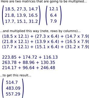
Here's a simple example,


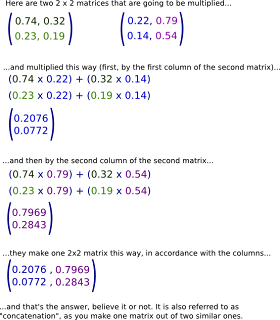
Now a 2 x 2 matrix to matrix multiplication (concatenation of two similar matrices into one)...


...and that constitutes a review.

Before making any attempt at hand made 3D graphics, procedures that multiply matrices in a program must be established. The following is a simple console program, that as usual can be strung together in the presented order and compiled to make the working demo application.

I am going to make three matrices; two that are going to be multiplied together, and a third to hold the output of the multiplication (concatenation) operation. First, it is a good idea to define a type out of the matrix, so that multiple, compatible instances of it can be created, make a function to populate the two matrices to be multiplied together with some values, and a function to display (cout) the contents of any of the matrices. This is simple stuff that anyone with an understanding of C++ just a little greater that "Hello World" can comprehend (which more or less guarantees that I will catch on again from here)...

#include "iostream"

using namespace std;

typedef int matrix[3][3];

void set_matrix(matrix x_mat, matrix y_mat)
{
x_mat[0][0] = 9;
x_mat[0][1] = 8;
x_mat[0][2] = 7;

x_mat[1][0] = 6;
x_mat[1][1] = 5;
x_mat[1][2] = 4;

x_mat[2][0] = 3;
x_mat[2][1] = 2;
x_mat[2][2] = 1;

y_mat[0][0] = 1;
y_mat[0][1] = 2;
y_mat[0][2] = 3;

y_mat[1][0] = 4;
y_mat[1][1] = 5;
y_mat[1][2] = 6;

y_mat[2][0] = 7;
y_mat[2][1] = 8;
y_mat[2][2] = 9;
}

void show_matrix(matrix mat)
{
int i, j;

for(i = 0; i < 3; i++)
{
for(j = 0; j < 3; j++)
{
cout << mat[i][j] << " ";
}
cout << endl;
}
cout << endl;
}


Then I will make a function that, in an expanded form, permits the easy following of what is happening during the matrix multiplication. The function accepts all three matrices as parameters, multiplies two of them (rows by columns, added together, in this case mat_1 and mat_2) and puts the results into the third (output matrix, in this case fin_mat)...

void expanded_mult(matrix mat_1, matrix mat_2, matrix fin_mat)
{
fin_mat[0][0] = (mat_1[0][0] * mat_2[0][0]) +
(mat_1[0][1] * mat_2[1][0]) +
(mat_1[0][2] * mat_2[2][0]);

fin_mat[1][0] = (mat_1[1][0] * mat_2[0][0]) +
(mat_1[1][1] * mat_2[1][0]) +
(mat_1[1][2] * mat_2[2][0]);

fin_mat[2][0] = (mat_1[2][0] * mat_2[0][0]) +
(mat_1[2][1] * mat_2[1][0]) +
(mat_1[2][2] * mat_2[2][0]);


fin_mat[0][1] = (mat_1[0][0] * mat_2[0][1]) +
(mat_1[0][1] * mat_2[1][1]) +
(mat_1[0][2] * mat_2[2][1]);

fin_mat[1][1] = (mat_1[1][0] * mat_2[0][1]) +
(mat_1[1][1] * mat_2[1][1]) +
(mat_1[1][2] * mat_2[2][1]);

fin_mat[2][1] = (mat_1[2][0] * mat_2[0][1]) +
(mat_1[2][1] * mat_2[1][1]) +
(mat_1[2][2] * mat_2[2][1]);


fin_mat[0][2] = (mat_1[0][0] * mat_2[0][2]) +
(mat_1[0][1] * mat_2[1][2]) +
(mat_1[0][2] * mat_2[2][2]);

fin_mat[1][2] = (mat_1[1][0] * mat_2[0][2]) +
(mat_1[1][1] * mat_2[1][2]) +
(mat_1[1][2] * mat_2[2][2]);

fin_mat[2][2] = (mat_1[2][0] * mat_2[0][2]) +
(mat_1[2][1] * mat_2[1][2]) +
(mat_1[2][2] * mat_2[2][2]);

}


All that is left to do is create the main() loop of the program now, and we are away with a 3x3 matrix multiplication program...

int main()
{
// locally create our three matrices of type matrix...
matrix x_matrix, y_matrix, final_matrix;

// populate the two matrices to be multiplied...
set_matrix(x_matrix, y_matrix);

// display the two matrices, so we can see they have been populated correctly...
show_matrix(x_matrix);
show_matrix(y_matrix);

// send all three matrices to the multiplier function, so that final_matrix can be populated with the results...
expanded_mult(x_matrix, y_matrix, final_matrix);

// and show the results of final matrix...
show_matrix(final_matrix);

return 0;
}


Does the trick? That's the whole program. Now some modifications to "compress" the code. I want to go after that void expanded_mult(matrix mat_1, matrix mat_2, matrix fin_mat) function to create something that is both a little more generic and less lengthy. for example, note that if you are doing a 4x4 matrix multiplication, that function is going to grow into an unwieldy...

//DEMO EXAMPLE
void expanded_mult(matrix mat_1, matrix mat_2, matrix fin_mat)
{
fin_mat[0][0] = (mat_1[0][0] * mat_2[0][0]) +
(mat_1[0][1] * mat_2[1][0]) +
(mat_1[0][2] * mat_2[2][0]) +
(mat_1[0][3] * mat_2[3][0]);

fin_mat[1][0] = (mat_1[1][0] * mat_2[0][0]) +
(mat_1[1][1] * mat_2[1][0]) +
(mat_1[1][2] * mat_2[2][0]) +
(mat_1[1][3] * mat_2[3][0]);

fin_mat[2][0] = (mat_1[2][0] * mat_2[0][0]) +
(mat_1[2][1] * mat_2[1][0]) +
(mat_1[2][2] * mat_2[2][0]) +
(mat_1[2][3] * mat_2[3][0]);

fin_mat[3][0] = (mat_1[3][0] * mat_2[0][0]) +
(mat_1[3][1] * mat_2[1][0]) +
(mat_1[3][2] * mat_2[2][0]) +
(mat_1[3][3] * mat_2[3][0]);


fin_mat[0][1] = (mat_1[0][0] * mat_2[0][1]) +
(mat_1[0][1] * mat_2[1][1]) +
(mat_1[0][2] * mat_2[2][1]) +
(mat_1[0][3] * mat_2[3][1]);

fin_mat[1][1] = (mat_1[1][0] * mat_2[0][1]) +
(mat_1[1][1] * mat_2[1][1]) +
(mat_1[1][2] * mat_2[2][1]) +
(mat_1[1][3] * mat_2[3][1]);

fin_mat[2][1] = (mat_1[2][0] * mat_2[0][1]) +
(mat_1[2][1] * mat_2[1][1]) +
(mat_1[2][2] * mat_2[2][1]) +
(mat_1[2][3] * mat_2[3][1]);

fin_mat[3][1] = (mat_1[3][0] * mat_2[0][1]) +
(mat_1[3][1] * mat_2[1][1]) +
(mat_1[3][2] * mat_2[2][1]) +
(mat_1[3][3] * mat_2[3][1]);


fin_mat[0][2] = (mat_1[0][0] * mat_2[0][2]) +
(mat_1[0][1] * mat_2[1][2]) +
(mat_1[0][2] * mat_2[2][2]) +
(mat_1[0][3] * mat_2[3][2]);

fin_mat[1][2] = (mat_1[1][0] * mat_2[0][2]) +
(mat_1[1][1] * mat_2[1][2]) +
(mat_1[1][2] * mat_2[2][2]) +
(mat_1[1][3] * mat_2[3][2]);

fin_mat[2][2] = (mat_1[2][0] * mat_2[0][2]) +
(mat_1[2][1] * mat_2[1][2]) +
(mat_1[2][2] * mat_2[2][2]) +
(mat_1[2][3] * mat_2[3][2]);

fin_mat[3][2] = (mat_1[3][0] * mat_2[0][2]) +
(mat_1[3][1] * mat_2[1][2]) +
(mat_1[3][2] * mat_2[2][2]) +
(mat_1[3][3] * mat_2[3][2]);


fin_mat[0][3] = (mat_1[0][0] * mat_2[0][3]) +
(mat_1[0][1] * mat_2[1][3]) +
(mat_1[0][2] * mat_2[2][3]) +
(mat_1[0][3] * mat_2[3][3]);

fin_mat[1][3] = (mat_1[1][0] * mat_2[0][3]) +
(mat_1[1][1] * mat_2[1][3]) +
(mat_1[1][2] * mat_2[2][3]) +
(mat_1[1][3] * mat_2[3][3]);

fin_mat[2][3] = (mat_1[2][0] * mat_2[0][3]) +
(mat_1[2][1] * mat_2[1][3]) +
(mat_1[2][2] * mat_2[2][3]) +
(mat_1[2][3] * mat_2[3][3]);

fin_mat[3][3] = (mat_1[3][0] * mat_2[0][3]) +
(mat_1[3][1] * mat_2[1][3]) +
(mat_1[3][2] * mat_2[2][3]) +
(mat_1[3][3] * mat_2[3][3]);

}


Phew! This function does the same thing, using for loops...

// DEMO EXAMPLE
void mult_matrix(matrix mat_1, matrix mat_2, matrix fin_mat)
{
int temp = 0;
int a, b, c;

for(a = 0; a < 3; a++)
{
for(b = 0; b < 3; b++)
{
for(c = 0; c < 3; c++)
{
temp += mat_1[b][c] * mat_2[c][a];
}
fin_mat[b][a] = temp;
temp = 0;
}
}
}


...for a 3x3 matrix, or...

// DEMO EXAMPLE
void mult_matrix(matrix mat_1, matrix mat_2, matrix fin_mat)
{
int temp = 0;
int a, b, c;

for(a = 0; a < 4; a++)
{
for(b = 0; b < 4; b++)
{
for(c = 0; c < 4; c++)
{
temp += mat_1[b][c] * mat_2[c][a];
}
fin_mat[b][a] = temp;
temp = 0;
}
}
}


...for a 4x4 matrix. Put this function in (the 3x3 version) instead of the expanded_mult() function, and modify main() to look like this...

int main()
{
matrix x_matrix, y_matrix, final_matrix;

set_matrix(x_matrix, y_matrix);
show_matrix(x_matrix);
show_matrix(y_matrix);

mult_matrix(x_matrix, y_matrix, final_matrix);

show_matrix(final_matrix);

return 0;
}


...and you're away.

To wrap up, here's a complete listing of how I am handling 4x4 (or any, symmetrical matrix, depending on the value of SYM_MAT).

#include "iostream"

using namespace std;

const int SYM_MAT = 4;

typedef int matrix[SYM_MAT][SYM_MAT];


void set_matrix(matrix x_mat, matrix y_mat)
{
x_mat[0][0] = 16;
x_mat[0][1] = 15;
x_mat[0][2] = 14;
x_mat[0][3] = 13;

x_mat[1][0] = 12;
x_mat[1][1] = 11;
x_mat[1][2] = 10;
x_mat[1][3] = 9;

x_mat[2][0] = 8;
x_mat[2][1] = 7;
x_mat[2][2] = 6;
x_mat[2][3] = 5;

x_mat[3][0] = 4;
x_mat[3][1] = 3;
x_mat[3][2] = 2;
x_mat[3][3] = 1;


y_mat[0][0] = 1;
y_mat[0][1] = 2;
y_mat[0][2] = 3;
y_mat[0][3] = 4;

y_mat[1][0] = 5;
y_mat[1][1] = 6;
y_mat[1][2] = 7;
y_mat[1][3] = 8;

y_mat[2][0] = 9;
y_mat[2][1] = 10;
y_mat[2][2] = 11;
y_mat[2][3] = 12;

y_mat[3][0] = 13;
y_mat[3][1] = 14;
y_mat[3][2] = 15;
y_mat[3][3] = 16;
}


void show_matrix(matrix mat)
{
int i, j;

for(i = 0; i < SYM_MAT; i++)
{
for(j = 0; j < SYM_MAT; j++)
{
cout << mat[i][j] << " ";
}
cout << endl;
}
cout << endl;
}


void mult_matrix(matrix mat_1, matrix mat_2, matrix fin_mat)
{
int temp = 0;
int a, b, c;

for(a = 0; a < SYM_MAT; a++)
{
for(b = 0; b < SYM_MAT; b++)
{
for(c = 0; c < SYM_MAT; c++)
{
temp += mat_1[b][c] * mat_2[c][a];
}
fin_mat[b][a] = temp;
temp = 0;
}
}
}


int main()
{
matrix x_matrix, y_matrix, final_matrix;

set_matrix(x_matrix, y_matrix);
show_matrix(x_matrix);
show_matrix(y_matrix);

mult_matrix(x_matrix, y_matrix, final_matrix);

show_matrix(final_matrix);

return 0;
}


That's all, for this post.

Saturday, 7 January 2012

2 Dimensional Matrix Rotation - Indexing Vertices


The previous post was all very well for taking a first step in matrices, but there were a couple of short comings, as follows;

First, it only rotated one single point (vertex). In a working program, we may want to rotate many vertices using the same rotation transformation that our matrix calculation provided. For example, a single object may be made up of several vertices, all at different displacements from the origin. Ideally, I want the transformation applied to all these points, to give the appearance of rotating the object.

Second, the coordinates of the vertex were permanently altered by the rotation transformation. This is not the ideal. I would want the “source object” to be static, with its coordinates fixed, feed those coordinates through the matrix calculation and apply the rotation, and finally output the modified vertices into a “destination object”, which would then subsequently be displayed.


I am going to modify that matrix_2d_handler() function so that it accepts a structure of source vertices in an array, modifies them, and copies the modified vertices to a similar, destination array structure. Naturally, it is going to be necessary to create this structure, and make sure that both the source and destination structures are made from the same struct type, and are of the same type. So, here's the structure...
  

struct vertices_2D

{

float x;

float y;

};

...here's the size I want that structure to be, plus how many coords per vertex...


const int NUM_VERTS = 17;

const int NUM_VERT_PTS = 2;

...and here is how I declare my two structures in main().


vertices_2D points[NUM_VERTS];

vertices_2D screen_points[NUM_VERTS];

Fairly straightforward. I feed those two structures into the modified matrix handler function, which is this...


void calc_screen_points(vertices_2D *_pts, vertices_2D *_scrn_pts, float _angle)

{

float Matrix_2D[2][2];

Matrix_2D[0][0] = cosf(_angle);

Matrix_2D[0][1] = -sinf(_angle);

Matrix_2D[1][0] = sinf(_angle);

Matrix_2D[1][1] = cosf(_angle);

int i;

for(i = 0; i < NUM_VERTS; i++)

{

_scrn_pts[i].x = (Matrix_2D[0][0] * _pts[i].x) + (Matrix_2D[0][1] * _pts[i].y);

_scrn_pts[i].y = (Matrix_2D[1][0] * _pts[i].x) + (Matrix_2D[1][1] * _pts[i].y);

}

}

...this way...


calc_screen_points(points, screen_points, deg_to_rad(angle));

Now the values in the array structure points never get altered, and the array structure screen_points are altered by angle. But there is one issue outstanding; populating the points array structure with the coordinates of the “shape”. Well, figure out the coordinates, and, remembering that for a 2D shape there are 2 points per vertex, make an array of the coordinates (I made this array global, in this case)...


float thrush_points[NUM_VERTS * NUM_VERT_PTS] =

{

-270.0f, 0.0f, // 0

-240.0f, -17.0f, // 1

-20.0f, -50.0f, // 2

18.0f, -90.0f, // 3

55.0f, -85.0f, // 4

85.0f, -50.0f, // 5

200.0f, -28.0f, // 6

225.0f, -95.0f, // 7

265.0f, -95.0f, // 8

275.0f, 10.0f, // 9

80.0f, 35.0f, // 10

-70.0f, 35.0f, // 11

-240.0f, 17.0f, // 12

35.0f, 35.0f, // 13

-70.0f, -5.0f, // 14

35.0f, 0.0f, // 15

-30.0f, -10.0f // 16

};

...and read these points into the array structure (I did it this way, this time around)...


void read_points(vertices_2D *_pts)

{

int i, j;

for(i = 0, j = 0; i < NUM_VERTS; i++, j = i * 2)

{

_pts[i].x = thrush_points[j];

_pts[i].y = thrush_points[j+1];

}

}

...called from within main() like this...


read_points(points);

Yes, it can be seen, I am not much of a fan of multi dimensional arrays, considering that in reality, they are just an abstraction, in any case.

Anyway, that's the core of it, but the shape is pretty uninteresting unless I connect the points with lines. Here's how I do that...


const int NUM_LINES = 18;

const int NUM_LINE_PTS = 2;

float line_order[NUM_LINES * NUM_LINE_PTS] =

{

0, 1,

1, 2,

2, 3,

3, 4,

4, 5,

5, 6,

6, 7,

7, 8,

8, 9,

9, 10,

10, 11,

11, 12,

12, 0,

1, 12,

11, 14,

14, 16,

16, 15,

15, 13

};

This is another globally made array, in this case. What is it doing? Each “pair” of numbers identifies two of the vertices from screen_points that need to be strung together with a line. So, to make the outline of my shape, vertex 0 will be connected to vertex 1 with a line, vertex 1 to 2, 2 to 3, and so on. Note, each vertex may easily be used more than once, to draw lines, so the number of lines may not coincide with the number of vertices available. That's okay.

To accept this data, I will make another structure...


struct screen_lines

{

int line_start;

int line_end;

};

...declare an instance of its type in main as...


screen_lines lines[NUM_LINES];

...read the data with this function...


void read_lines(screen_lines *_lines)

{

int i, j;

for(i = 0, j = 0; i < NUM_LINES; i++, j = i * 2)

{

_lines[i].line_start = line_order[j];

_lines[i].line_end = line_order[j+1];

}

}


// Called this way from inside main()

read_lines(lines);

The lines are finally drawn to the screen with this function...


void draw_lines(vertices_2D *_scrn_pts, screen_lines *_lines, float x_cor, float y_cor)

{

int i;

float x1, y1, x2, y2;

for(i = 0; i < NUM_LINES; i++)

{

x1 = _scrn_pts[_lines[i].line_start].x;

y1 = _scrn_pts[_lines[i].line_start].y;

x2 = _scrn_pts[_lines[i].line_end].x;

y2 = _scrn_pts[_lines[i].line_end].y;


al_draw_line(x1 + x_cor, y1 + y_cor, x2 + x_cor, y2 + y_cor, al_map_rgb(0,255,0), 0);

}

}

...which indexes the coordinates of the vertices to the lines array, and draws the corresponding line for each couple. The x_cor and y_cor parameters are just for centering the shape on the screen, placing the origin dead center, and not up in the left corner as it would be without them.

Here's a screen shot and the full, working code for Allegro 5.1, to see the results...


...and how all the above fits in;


#define _USE_MATH_DEFINES
#include
#include
#include

/*
`pkg-config --libs allegro-5.1 allegro_primitives-5.1`
*/

struct vertices_2D
{
float x;
float y;
};

struct screen_lines
{
int line_start;
int line_end;
};

const int NUM_VERTS = 17;
const int NUM_VERT_PTS = 2;
const int NUM_LINES = 18;
const int NUM_LINE_PTS = 2;

enum KB_KEYS {KEY_Q, KEY_W};

float thrush_points[NUM_VERTS * NUM_VERT_PTS] =
{
-270.0f, 0.0f, // 0
-240.0f, -17.0f, // 1
-20.0f, -50.0f, // 2
18.0f, -90.0f, // 3
55.0f, -85.0f, // 4
85.0f, -50.0f, // 5
200.0f, -28.0f, // 6
225.0f, -95.0f, // 7
265.0f, -95.0f, // 8
275.0f, 10.0f, // 9
80.0f, 35.0f, // 10
-70.0f, 35.0f, // 11
-240.0f, 17.0f, // 12
35.0f, 35.0f, // 13
-70.0f, -5.0f, // 14
35.0f, 0.0f, // 15
-30.0f, -10.0f // 16
};

float line_order[NUM_LINES * NUM_LINE_PTS] =
{
0, 1,
1, 2,
2, 3,
3, 4,
4, 5,
5, 6,
6, 7,
7, 8,
8, 9,
9, 10,
10, 11,
11, 12,
12, 0,
1, 12,
11, 14,
14, 16,
16, 15,
15, 13

};

//*******************
float deg_to_rad(float deg)
{
return deg * ((float)M_PI / 180.0f);
}


//****************
void read_points(vertices_2D *_pts)
{
int i, j;
for(i = 0, j = 0; i < NUM_VERTS; i++, j = i * 2)
{
_pts[i].x = thrush_points[j];
_pts[i].y = thrush_points[j+1];
}
}

//****************
void read_lines(screen_lines *_lines)
{
int i, j;
for(i = 0, j = 0; i < NUM_LINES; i++, j = i * 2)
{
_lines[i].line_start = line_order[j];
_lines[i].line_end = line_order[j+1];
}
}

//****************
void calc_screen_points(vertices_2D *_pts, vertices_2D *_scrn_pts, float _angle)
{
float Matrix_2D[2][2];
Matrix_2D[0][0] = cosf(_angle);
Matrix_2D[0][1] = -sinf(_angle);
Matrix_2D[1][0] = sinf(_angle);
Matrix_2D[1][1] = cosf(_angle);

int i;
for(i = 0; i < NUM_VERTS; i++)
{
_scrn_pts[i].x = (Matrix_2D[0][0] * _pts[i].x) + (Matrix_2D[0][1] * _pts[i].y);
_scrn_pts[i].y = (Matrix_2D[1][0] * _pts[i].x) + (Matrix_2D[1][1] * _pts[i].y);
}
}

//****************
void draw_lines(vertices_2D *_scrn_pts, screen_lines *_lines, float x_cor, float y_cor)
{
int i;
float x1, y1, x2, y2;

for(i = 0; i < NUM_LINES; i++)
{
x1 = _scrn_pts[_lines[i].line_start].x;
y1 = _scrn_pts[_lines[i].line_start].y;
x2 = _scrn_pts[_lines[i].line_end].x;
y2 = _scrn_pts[_lines[i].line_end].y;

al_draw_line(x1 + x_cor, y1 + y_cor, x2 + x_cor, y2 + y_cor, al_map_rgb(0,255,0), 0);
}

}

//*******************
int main(int argc, char *argv[])
{
ALLEGRO_DISPLAY *display = NULL;
ALLEGRO_EVENT_QUEUE *event_queue = NULL;
ALLEGRO_TIMER *timer = NULL;

vertices_2D points[NUM_VERTS];
vertices_2D screen_points[NUM_VERTS];
screen_lines lines[NUM_LINES];

read_points(points);
read_lines(lines);

int SCREEN_X = 800;
int SCREEN_Y = 600;
int SC_X_CENT = SCREEN_X / 2;
int SC_Y_CENT = SCREEN_Y / 2;

float FPS = 60.0f;
float angle = 0.0f;

bool key[2] = {false, false};

bool draw = false;
bool loop = true;

al_init();
al_init_primitives_addon();
al_install_keyboard();

al_set_new_display_option(ALLEGRO_VSYNC, 1, ALLEGRO_SUGGEST);

display = al_create_display(SCREEN_X, SCREEN_Y);
event_queue = al_create_event_queue();
timer = al_create_timer(1.0f / FPS);

al_register_event_source(event_queue, al_get_display_event_source(display));
al_register_event_source(event_queue, al_get_timer_event_source(timer));
al_register_event_source(event_queue, al_get_keyboard_event_source());

al_start_timer(timer);

while(loop)
{
ALLEGRO_EVENT event;
al_wait_for_event(event_queue, &event);

switch(event.type)
{
case ALLEGRO_EVENT_DISPLAY_CLOSE:
loop = false;
break;

case ALLEGRO_EVENT_TIMER:
draw = true;
break;

case ALLEGRO_EVENT_KEY_DOWN:
switch(event.keyboard.keycode)
{
case ALLEGRO_KEY_Q:
key[KEY_Q] = true;
break;

case ALLEGRO_KEY_W:
key[KEY_W] = true;
break;

default:
break;
}
break;

case ALLEGRO_EVENT_KEY_UP:
switch(event.keyboard.keycode)
{
case ALLEGRO_KEY_Q:
key[KEY_Q] = false;
break;

case ALLEGRO_KEY_W:
key[KEY_W] = false;
break;

default:
break;
}
break;

default:
break;
}

if(draw == true && al_event_queue_is_empty(event_queue))
{
draw = false;

if(key[KEY_Q])
{
angle -= 0.5f;
if(angle < 0.0f)
angle += 360;
}
if(key[KEY_W])
{
angle += 0.5f;
if(angle > 359.99f)
angle -= 360;
}

al_clear_to_color(al_map_rgb(0,0,0));
calc_screen_points(points, screen_points, deg_to_rad(angle));
draw_lines(screen_points, lines, SC_X_CENT, SC_Y_CENT);

al_flip_display();
}
}

al_stop_timer(timer);
al_flush_event_queue(event_queue);
al_destroy_timer(timer);
al_destroy_event_queue(event_queue);
al_destroy_display(display);

return 0;
}


That's all for now, except never EVER draft your blogs in LibreOffice Writer again. 3D next time...


2 Dimensional Matrix Rotation - Simple

Now, if curiosity killed the cat, but the cat has nine lives, that makes the cat eight times the wiser before it finally does get killed. Sounds like a fair trade to me, just so long as the curiosity is well spent. Doing all that OpenGL stuff that was in my previous posts is all well and dandy, but would it not be nice to at least have a superficial idea of what (sort of) goes on "under the hood" in order to supplement one's global understanding of 3D computer graphics? The following two or three posts, therefore, will concentrate on the heart of the matter where OpenGL rotation transformations are concerned...

THE MATRIX

There are tons of pages that "blah - blah" on about what matrices are, how they are arranged and multiplied, etcetera, but no simple example of their implementation. In this post, I am going to attack the simplest form of them, the 2D matrix, to enable the rotation of one point around the Z axis. It will probably be obvious that the matrix itself is the least of the worries. It is easy, for 2D stuff. Here's what happens, really.

Consider first the origin. That is, point (0, 0) on the X and Y axes. I have a point that is located at (150.0, -200.0) from that origin, which I want to rotate around the Z axis by 0.5 of a degree, every 1/60th of a second. The 2D matrix takes on this form...

- X - Y
X : cos(angle) : -sin(angle)
Y : sin(angle) : cos(angle)

To which the data of the old positions can be plugged in to achieve a rotation like this...

NEW_X_POSITION = (cos(angle) * old_x_position) + (-sin(angle) * old_y_position)
NEW_Y_POSITION = (sin(angle) * old_x_position) + (cos(angle) * old_y_position)

Do the math itself, on a piece of paper with a calculator, and the understanding will dawn. It is so simple, at this stage, that no further discussion is required. Here's some working source code, using Allegro 5.1.

#define _USE_MATH_DEFINES
#include "allegro5/allegro.h"
#include "allegro5/allegro_primitives.h"
#include "math.h"

/*
`pkg-config --libs allegro-5.1 allegro_primitives-5.1`
*/

//*******************
float deg_to_rad(float deg)
{
return deg * ((float)M_PI / 180.0f);
}


void matrix_2d_handler(float _angle, float &_x_pos, float &_y_pos)
{
float Matrix_2D[2][2];
float New_X, New_Y;

Matrix_2D[0][0] = cosf(_angle); Matrix_2D[0][1] = -sinf(_angle);
Matrix_2D[1][0] = sinf(_angle); Matrix_2D[1][1] = cosf(_angle);

New_X = (Matrix_2D[0][0] * _x_pos) + (Matrix_2D[0][1] * _y_pos);
New_Y = (Matrix_2D[1][0] * _x_pos) + (Matrix_2D[1][1] * _y_pos);

_x_pos = New_X;
_y_pos = New_Y;
}


//*******************
int main(int argc, char *argv[])
{
ALLEGRO_DISPLAY *display = NULL;
ALLEGRO_EVENT_QUEUE *event_queue = NULL;
ALLEGRO_TIMER *timer = NULL;

int SCREEN_X = 800;
int SCREEN_Y = 600;
int SC_X_CENT = SCREEN_X / 2;
int SC_Y_CENT = SCREEN_Y / 2;

float FPS = 60.0f;
float X_pos = 150.0f;
float Y_pos = -200.0f;
float angle = 0.5f;

bool draw = false;
bool loop = true;

al_init();
al_init_primitives_addon();


al_set_new_display_option(ALLEGRO_VSYNC, 1, ALLEGRO_SUGGEST);

display = al_create_display(SCREEN_X, SCREEN_Y);
event_queue = al_create_event_queue();
timer = al_create_timer(1.0f / FPS);

al_register_event_source(event_queue, al_get_display_event_source(display));
al_register_event_source(event_queue, al_get_timer_event_source(timer));

al_start_timer(timer);

while(loop)
{
ALLEGRO_EVENT event;
al_wait_for_event(event_queue, &event);

switch(event.type)
{
case ALLEGRO_EVENT_DISPLAY_CLOSE:
loop = false;
break;

case ALLEGRO_EVENT_TIMER:
draw = true;
break;

default:
break;
}

if(draw == true && al_event_queue_is_empty(event_queue))
{
draw = false;
al_clear_to_color(al_map_rgb(0,0,0));
matrix_2d_handler(deg_to_rad(angle), X_pos, Y_pos);
al_draw_circle(float(X_pos + SC_X_CENT), float(Y_pos + SC_Y_CENT), 10.0f, al_map_rgb(0,255,0), 0);
al_flip_display();
}
}

al_stop_timer(timer);
al_flush_event_queue(event_queue);
al_destroy_timer(timer);
al_destroy_event_queue(event_queue);
al_destroy_display(display);

return 0;
}

Wednesday, 4 January 2012

OpenGL / Allegro 5.1 Vertex Array with texture coords

After spending some time making my own procedure to interpret arrays of vertices, to simplify making slightly more complex shapes other than cubes, and passing them to glVertex3f() sequentially, I suddenly came across - in the GL docs - a neat feature of OpenGL which had already considered this possibility;

glEnableClientState()

All the various options that it can handle are listed there, but what interested me most at this stage was passing the vertex and texture coordinates to make the Python space craft from the old space trader game, Elite, by David Braben,(a classic I used to play on the Spectrum: could it be at all possible that anyone has not heard of it?).

So, with that, I will bypass my own functions for handling arrays (which I WAS going to post here) and stick to OpenGL's functions, as that is what I am learning. First, I (hand) drew the python in plan and side elevation on a piece of squared paper, and figured out the various points in X-Y-Z coordinates. These are in the array GLfloat python_verts[] in the code posted below. Fairly simple, that part. Here are the basics of how to implement that into code;

// tell GL what you are planning to do with the array you are going to pass it...
glEnableClientState(GL_VERTEX_ARRAY);

// create a pointer to the array with the following GL function...
glVertexPointer(3, GL_FLOAT, 0, python_verts);


Basically, that pointer is causing OpenGL to select the correct glVertex..() to interpret your array. In this case glVertex3f(), because we specify that the vertices are in sets of three, and are GLfloat type, and that they are listed in the python_verts array.

Now, I made my python with a series of triangles (respecting the outward faces vertex order being counter clockwise, of cour se!), so now to draw the Python;

glDrawArrays(GL_TRIANGLES, 0, 54);

Where did the 54 come from? The Python is made up of 18 triangles, each of 3 vertices, so it has to iterate 54 time to draw each individual triangle. Finally, disable the set Clientstate...

glDisableClientState(GL_VERTEX_ARRAY);


Everything made easy. It even automatically invokes glBegin() and glEnd(), so there is no need to call this specifically to draw the triangles...

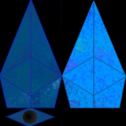
Then (with Pinta) I drew the experimental texture I wanted to try out mapped onto the Python. I made a 256 x 256 texture so that I can later experiment a bit more with mip-mapping. Here 'tis...


Now, to map this, a couple of additional topics need to be covered. First, one must be very methodical (and patient) while doing this.

Next, remember that the coordinates of (2D) textures are mapped this way...
...with the Y axis 0 being at the bottom, and not the top like most paint programs have it. The easiest approach to overcome this issue is probably to temporarily flip the texture vertically while you plot the positions on the texture, and once you have the coordinates, flip it back again the way it was. Why do I say this? You are going to be working with some numbers to get the pixel positions in coefficients of the image size. I will do an example of texture mapping on one face to clarify. Here's the flipped image...


I am going to texture map the very first triangle drawn, which is the upper left nose of the Python. In the picture above, it is the first triangle encountered as from the lower left of the graphic.

But before I start mapping, i am going to look at the order of the drawing of the vertices for that triangle...
0.0f,0.0f,-9.0f, -3.0f,0.0f,0.0f, 0.0f,1.5f,-2.0f,

It goes from the nose, to the "wing-tip", to the center line on the front cabin. That is the same order I want to map the texture with. Bearing this in mind, I will make a texture coordinate for each of those points, in the format required by glTexCoord2f().

Starting at the nose of the Python, in the flipped texture graphic, I obtain the texture coordinates by dividing the actual pixel position of the required point (in X, Y) order by the total corresponding size of the image. For the very nose tip;

X = 63 / 256 = 0.246
Y = 256 / 256 = 1.000


Write that down like this...
0.246f, 1.000f

Now the wing-tip, keeping in with following the order of the drawn vertices...

X = 0 / 256 = 0.000
Y = 102 / 256 = 0.398

And the last center line point...

X = 63 / 256 = 0.246
Y = 140 / 256 = 0.547

So, here are the UV coordinates for the "section" of the texture to be mapped to the upper left nose of the python...

0.246f, 1.000f, 0.000f, 0.398f, 0.246f, 0.547f


...and that needs to be done for each and ev ery vertex of the whole object, with its corresponding bit of the texture. Once all the points are mapped, put them into another array, for example python_tex_coords[]. Don't forget to Y axis flip the texture back to how it was, either. And now take a break after doing it or you'll go barmy.

Finally, to activate the texture mapping in OpenGL, enable another Client State (along with the previously demonstrated one) and make a pointer to the texture coordinates. Here's how...

glEnableClientState(GL_VERTEX_ARRAY);
glEnableClientState(GL_TEXTURE_COORD_ARRAY);

glVertexPointer(3, GL_FLOAT, 0, python_verts);
glTexCoordPointer(2, GL_FLOAT, 0, python_tex_coords);

glDrawArrays(GL_TRIANGLES, 0, 54);

glDisableClientState(GL_TEXTURE_COORD_ARRAY);
glDisableClientState(GL_VERTEX_ARRAY);

Notice only that the first parameter of glTexCoordPointer() is 2. this is because there are only two uv coords for every vertex point (which are, themselves, three). It works the same as glVertexPointer, in all other respects.

Here's a screen shot (Blue Danube, anyone?)...

And that is it. I deliberately left some commented out things I was playing with in the code posted below, for reference, as there are more ways to draw from arrays that OpenGL, in its wisdom, can do.

#include "allegro5/allegro.h"
#include "allegro5/allegro_opengl.h"
#include "allegro5/allegro_image.h"
#include "GL/glu.h"

int SCREEN_X = 800;
int SCREEN_Y = 600;

GLfloat python_verts[] =
{
// Nose
// upper left
0.0f,0.0f,-9.0f, -3.0f,0.0f,0.0f, 0.0f,1.5f,-2.0f,
//upper right
0.0f,0.0f,-9.0f, 0.0f,1.5f,-2.0f, 3.0f,0.0f,0.0f,
// lower left
0.0f,0.0f,-9.0f, 0.0f,-1.5f,-2.0f, -3.0f,0.0f,0.0f,
// lower right
0.0f,0.0f,-9.0f, 3.0f,0.0f,0.0f, 0.0f,-1.5f,-2.0f,
// Cabin
// upper left
-3.0f,0.0f,0.0f, 0.0f,1.5f,2.0f, 0.0f,1.5f,-2.0f,
// upper right
3.0f,0.0f,0.0f, 0.0f,1.5f,-2.0f, 0.0f,1.5f,2.0f,
// lower left
-3.0f,0.0f,0.0f, 0.0f,-1.5f,-2.0f, 0.0f,-1.5f,2.0f,
// lower right
3.0f,0.0f,0.0f, 0.0f,-1.5f,2.0f, 0.0f,-1.5f,-2.0f,
// Tail forward
// upper left
-3.0f,0.0f,0.0f, -2.0f,0.0f,4.0f, 0.0f,1.5f,2.0f,
// upper right
3.0f,0.0f,0.0f, 0.0f,1.5f,2.0f, 2.0f,0.0f,4.0f,
// lower left
-3.0f,0.0f,0.0f, 0.0f,-1.5f,2.0f, -2.0f,0.0f,4.0f,
//lower right
3.0f,0.0f,0.0f, 2.0f,0.0f,4.0f, 0.0f,-1.5f,2.0f,
// Tail rear
// upper left
-2.0f,0.0f,4.0f, 0.0f,0.8f,4.0f, 0.0f,1.5f,2.0f,
// upper right
0.0f,1.5f,2.0f, 0.0f,0.8f,4.0f, 2.0f,0.0f,4.0f,
// lower left
-2.0f,0.0f,4.0f, 0.0f,-1.5f,2.0f, 0.0f,-0.8f,4.0f,
// lower right
0.0f,-1.5f,2.0f, 2.0f,0.0f,4.0f, 0.0f,-0.8f,4.0f,
// stern
// left
-2.0f,0.0f,4.0f, 0.0f,-0.8f,4.0f, 0.0f,0.8f,4.0f,
//right
2.0f,0.0f,4.0f, 0.0f,0.8f,4.0f, 0.0f,-0.8f,4.0f
};

GLfloat python_tex_coords[] =
{
// Nose
// upper left
0.246f,1.000f, 0.000f,0.398f, 0.246f,0.547f,
// upper right
0.246f,1.000f, 0.246f,0.547f, 0.488f,0.398f,
// lower left
0.746f,1.000f, 0.746f,0.547f, 1.000f,0.398f,
// lower right
0.746f,1.000f, 0.492,0.398f, 0.746f,0.547f,
// Cabin
// upper left
0.000f,0.398f, 0.246f,0.242f, 0.246f,0.547f,
// upper right
0.488f,0.398f, 0.246f,0.547f, 0.246f,0.242f,
// lower left
1.000f,0.398f, 0.746f,0.547f, 0.746f,0.242f,
// lower right
0.492f,0.398f, 0.746f,0.242f, 0.746f,0.547f,
// Tail forward
// upper left
0.000f,0.398f, 0.055f,0.145f, 0.246f,0.242f,
// upper right
0.488f,0.398f, 0.246f,0.242f, 0.429f,0.145f,
// lower left
1.000f,0.398f, 0.746f,0.242f, 0.945f,0.145f,
// lower right
0.492f,0.398f, 0.559f,0.145f, 0.746f,0.242f,
// Tail rear
// upper left
0.055f,0.145f, 0.246f,0.140f, 0.246f,0.242f,
// upper right
0.246f,0.242f, 0.246f,0.140f, 0.429f,0.145f,
// lower left
0.945f,0.145f, 0.746f,0.242f, 0.746f,0.145f,
// lower right
0.746f,0.242f, 0.559f,0.145f, 0.746f,0.145f,
// Stern
// left
0.062f,0.074f, 0.246f,0.000f, 0.246f,0.140f,
// right
0.418f,0.074f, 0.246f,0.140f, 0.246f,0.000f
};


void camera_3D_setup()
{
glMatrixMode(GL_PROJECTION);
glLoadIdentity();
gluPerspective(35.0, (GLdouble)SCREEN_X / (GLdouble)SCREEN_Y, 1.0, 100.0);
}

void draw_python(GLuint ogl_tex, GLfloat x_ang, GLfloat y_ang, GLfloat z_ang)
{
glClear(GL_COLOR_BUFFER_BIT | GL_DEPTH_BUFFER_BIT);
al_clear_to_color(al_map_rgb(0,0,30));

glMatrixMode(GL_MODELVIEW);
glLoadIdentity();

glTranslatef(0.0f, 0.0f, -30.0f);
glRotatef(x_ang, 1.0f, 0.0f, 0.0f);
glRotatef(y_ang, 0.0f, 1.0f, 0.0f);
glRotatef(z_ang, 0.0f, 0.0f, 1.0f);

glEnable(GL_CULL_FACE);
glEnable(GL_DEPTH_TEST);
glEnable(GL_TEXTURE_2D);

glBindTexture(GL_TEXTURE_2D, ogl_tex);

// No need to do glBegin() or glEnd() when using these GL functions
// They appear to intrinsic to the functions, like glDrawElements
// In a similar fashion to gluQuadricObjects, like gluSphere().
glEnableClientState(GL_VERTEX_ARRAY);
//glEnableClientState(GL_COLOR_ARRAY);
glEnableClientState(GL_TEXTURE_COORD_ARRAY);

glVertexPointer(3, GL_FLOAT, 0, python_verts);
glTexCoordPointer(2, GL_FLOAT, 0, python_tex_coords);
//glColorPointer(3, GL_FLOAT, 0, python_colors);

//glDrawElements(GL_TRIANGLES, 54, GL_UNSIGNED_INT, python_vert_index);
glDrawArrays(GL_TRIANGLES, 0, 54);

glDisableClientState(GL_TEXTURE_COORD_ARRAY);
//glDisableClientState(GL_COLOR_ARRAY);
glDisableClientState(GL_VERTEX_ARRAY);

glDisable(GL_TEXTURE_2D);
glDisable(GL_DEPTH_TEST);
glDisable(GL_CULL_FACE);

glFlush();
}

int main(int argc, char *argv[])
{
float FPS = 60.0f;
bool loop = true;
bool draw = false;

GLfloat x_angle = 70.0f;
GLfloat y_angle = 0.0f;
GLfloat z_angle = 180.0f;
GLuint python_tex;

ALLEGRO_DISPLAY *display = NULL;
ALLEGRO_TIMER *timer = NULL;
ALLEGRO_EVENT_QUEUE *event_queue = NULL;
ALLEGRO_BITMAP *python_bmp = NULL;

al_init();
al_init_image_addon();

al_set_new_display_flags(ALLEGRO_OPENGL);
display = al_create_display(SCREEN_X, SCREEN_Y);
timer = al_create_timer(1.0f / FPS);
event_queue = al_create_event_queue();

python_bmp = al_load_bitmap("pythontexture.jpg");
python_tex = al_get_opengl_texture(python_bmp);

al_register_event_source(event_queue, al_get_display_event_source(display));
al_register_event_source(event_queue, al_get_timer_event_source(timer));

al_start_timer(timer);

camera_3D_setup();

while(loop)
{
ALLEGRO_EVENT event;
al_wait_for_event(event_queue, &event);

switch(event.type)
{
case ALLEGRO_EVENT_DISPLAY_CLOSE:
loop = false;
break;

case ALLEGRO_EVENT_TIMER:
draw = true;
break;

default:
break;
}

if(draw == true && al_event_queue_is_empty(event_queue))
{
draw = false;
x_angle += 0.25f;
//y_angle -= 0.35f;
z_angle += 0.5f;
draw_python(python_tex, x_angle, y_angle, z_angle);
al_flip_display();
}
}


return 0;
}

Peaceful, non-violent, involving and enthralling subjugation and distraction for the masses, if only they will have the nerve to try it...