About this Blog

This is my first blog. Ever.

It is simply going to be about my hobby; playing with computer programming. I do not know much about blogging, but I will use this one to learn a bit more about it.

Programming has always been a bit of a passion for me, as from those early days when I first tapped in a sample BASIC program on my old Sinclair Spectrum back in 1986. I have been through many platforms, languages and OS's since, but always carried the hobby with me. I am not particularly good at it; perfection requires a large time investment and continuous practice. I do not have the luxury of the amount of time required to keep the fire burning constantly, so the hobby has inevitably gone through periods of extreme withering. I have, however, finally settled for C++, as the title of this blog implies, and play around with it for some entertainment when ever I can.

This here will serve me as a written record of what I am up to, and hopefully be a reinforcement to my memory every now and then. That is all there is to it.

So, if you read this blog, please don't expect anything snazzy, but be you welcome just the same!

Tuesday 27 December 2011

OpenGL / Allegro 5.1 3D Orbit Primer

So, here again, and still learning (and what is more; still capable of learning, which is always good to know). There is little new with this post, as compared to others. It is more of a confluence of some techniques learned in those other posts to make an animation of a dry earth planet in an elliptical orbit around a shrunken "brown dwarf" style sun. Let's say it is an improbable future scenario?

Here are the textures used, followed by the source code...


#include "allegro5/allegro.h"
#include "allegro5/allegro_image.h"
#include "allegro5/allegro_opengl.h"
#include "GL/glu.h"
#include "math.h"

/*
`pkg-config --libs allegro-5.1 allegro_image-5.1`
-lGL
-lGLU
*/

int SCREEN_X = 800;
int SCREEN_Y = 600;

class planets
{
public:
// a = G (m/r²) : Reference formula
float radius_1;
float radius_2;
float angle_1;
float angle_2;

float grav_const; // = 6.6742e-11; // The "G" in the
formula
float star_mass; // = 5.975e24; // The "m" in the formula

float grav_accel; // The "a" in the formula
float body_x;
float body_z;
float body_y;
float b_vel_x;
float b_vel_z;
float b_vel_y;

planets(void);
~planets(void);

void calc_planet_pos();
};

// Define class functions:

planets::planets(void)
{
grav_const = 6.6742e-11;
star_mass = 5.975e24;
body_x = 1.5e6;
body_z = 5.5e4;
body_y = 1.0e6;
b_vel_x = -3000;
b_vel_z = 11000.0;
b_vel_y = 3000.0;
}

planets::~planets(void)
{
// nothing doing...
}

void planets::calc_planet_pos()
{
angle_1 = atan2f(body_x, body_z);
radius_1 = sqrtf(pow(body_x, 2) + pow(body_z, 2));
angle_2 = atan2f(body_y, radius_1);
radius_2 = sqrtf(pow(body_x, 2) + pow(body_z, 2) + pow(body_y, 2));

grav_accel = (grav_const * (star_mass / pow(radius_2, 2)));

b_vel_x = b_vel_x + ((sin(angle_1) * cos(angle_2)) * (grav_accel));
b_vel_z = b_vel_z + ((cos(angle_1) * cos(angle_2)) * (grav_accel));
b_vel_y = b_vel_y + (sin(angle_2) * (grav_accel));

body_x = body_x - b_vel_x;
body_z = body_z - b_vel_z;
body_y = body_y - b_vel_y;
}

//******* END OF CLASS ********


//******* FUNCTIONS ********

void camera_3D_setup()
{
glMatrixMode(GL_PROJECTION);
glLoadIdentity();
gluPerspective(35.0, (GLdouble)SCREEN_X / (GLdouble)SCREEN_Y, 1.0, 2000.0);
glTranslatef(-80.0f, -70.0f, -650.0f);

}

void camera_2D_setup()
{
glMatrixMode(GL_PROJECTION);
glLoadIdentity();
glOrtho(0.0, (GLdouble)SCREEN_X, (GLdouble)SCREEN_Y, 0.0, 0.0, 1.0);
//glTranslatef(0.0f, 0.0f, 20.0f);
}


void draw_planets(planets *Orbit, GLUquadricObj *q_earth, GLUquadricObj *q_sun, GLuint *o_tex, ALLEGRO_BITMAP *back_gnd, GLfloat e_ang, GLfloat s_ang)
{
glClear(GL_COLOR_BUFFER_BIT | GL_DEPTH_BUFFER_BIT);
al_clear_to_color(al_map_rgb(0,0,0));
camera_2D_setup();
al_draw_bitmap(back_gnd, 0.0f, 0.0f, 0);

Orbit->calc_planet_pos();
camera_3D_setup();
glEnable(GL_DEPTH_TEST);
glEnable(GL_TEXTURE_2D);

//glTexParameterf(GL_TEXTURE_2D, GL_TEXTURE_MIN_FILTER, GL_LINEAR_MIPMAP_LINEAR);
//glTexParameterf(GL_TEXTURE_2D, GL_TEXTURE_MAG_FILTER, GL_LINEAR);

glBindTexture(GL_TEXTURE_2D, *(o_tex));
glTexParameterf(GL_TEXTURE_2D, GL_TEXTURE_MIN_FILTER, GL_LINEAR_MIPMAP_LINEAR);
glTexParameterf(GL_TEXTURE_2D, GL_TEXTURE_MAG_FILTER, GL_LINEAR);

glMatrixMode(GL_MODELVIEW);
glLoadIdentity();

glPushMatrix();
glTranslatef(Orbit->body_x / 5000.0f, Orbit->body_y / 5000.0f, Orbit->body_z / 5000.0f);
glRotatef(-90.0f, 1.0f, 0.0f, 0.0f);
glRotatef(23.0f, 0.0f, 1.0f, 0.0f);
glRotatef(e_ang, 0.0f, 0.0f, 1.0f);


gluQuadricTexture(q_earth, GL_TRUE);
gluSphere(q_earth,8.0f,20,20);
gluQuadricTexture(q_earth, GL_FALSE);
glPopMatrix();


glPushMatrix();
glBindTexture(GL_TEXTURE_2D, *(o_tex+1));
glTexParameterf(GL_TEXTURE_2D, GL_TEXTURE_MIN_FILTER, GL_LINEAR_MIPMAP_LINEAR);
glTexParameterf(GL_TEXTURE_2D, GL_TEXTURE_MAG_FILTER, GL_LINEAR);

glTranslatef(0.0f, 0.0f, 0.0f);
glRotatef(-80.0f, 1.0f, 0.0f, 0.0f);
glRotatef(-15.0f, 0.0f, 1.0f, 0.0f);
glRotatef(s_ang, 0.0f, 0.0f, 1.0f);

gluQuadricTexture(q_sun, GL_TRUE);
gluSphere(q_sun,70.0f,28,28);
gluQuadricTexture(q_sun, GL_FALSE);
glPopMatrix();

glDisable(GL_TEXTURE_2D);
glDisable(GL_DEPTH_TEST);

glFlush();

}

// ****** END OF FUNCTIONS ******

int main(int argc, char *argv[])
{
ALLEGRO_DISPLAY *display = NULL;
ALLEGRO_EVENT_QUEUE *event_queue = NULL;
ALLEGRO_TIMER *timer = NULL;
ALLEGRO_BITMAP *bmp[3];

planets A5_Orbit;

int i = 0;
float FPS = 60.0f;
bool loop = true;
bool draw = false;

GLfloat e_rot_angle = 0.0f;
GLfloat s_rot_angle = 0.0f;

GLUquadricObj *quad_earth;
GLUquadricObj *quad_sun;

GLuint ogl_tex[2];

quad_earth = gluNewQuadric();
quad_sun = gluNewQuadric();

// Note; no error trapping as yet...
al_init();
al_init_image_addon();

al_set_new_display_flags(ALLEGRO_OPENGL);
al_set_new_display_option(ALLEGRO_VSYNC, 1, ALLEGRO_SUG
GEST);
display = al_create_display(SCREEN_X, SCREEN_Y);
event_queue = al_create_event_queue();
timer = al_create_timer(1.0f/FPS);

al_set_new_bitmap_flags(ALLEGRO_MIPMAP | ALLEGRO_MIN_LINEAR);
bmp[0] = al_load_bitmap("img_1.jpg");
bmp[1] = al_load_bitmap("img_2.jpg");
al_set_new_bitmap_flags(ALLEGRO_CONVERT_BITMAP);
bmp[2] = al_load_bitmap("img_stars.jpg");

for(i = 0; i < 2; i++)
{
ogl_tex[i] = al_get_opengl_texture(bmp[i]);
}

al_register_event_source(event_queue, al_get_display_event_source(display));
al_register_event_source(event_queue, al_get_timer_event_source(timer));

al_start_timer(timer);

while(loop == true)
{
ALLEGRO_EVENT event;
al_wait_for_event(event_queue, &event);

switch(event.type)
{
case ALLEGRO_EVENT_DISPLAY_CLOSE:
loop = false;
break;

case ALLEGRO_EVENT_TIMER:
draw = true;
break;

default:
break;

}

if(draw == true && al_event_queue_is_empty(event_queue))
{
e_rot_angle += 0.75f;
s_rot_angle -= 0.15f;
draw = false;
draw_planets(&A5_Orbit, quad_earth, quad_sun, ogl_tex, bmp[2], e_rot_angle, s_rot_angle);

al_flip_display();

}
}

for(i = 0; i < 3; i++)
al_destroy_bitmap(bmp[i]);

glDeleteTextures(2, ogl_tex);
gluDeleteQuadric(quad_earth);
gluDeleteQuadric(quad_sun);

al_flush_event_queue(event_queue);
al_destroy_event_queue(event_queue);
al_stop_timer(timer);
al_destroy_timer(timer);
al_destroy_display(display);

return 0;
}

So, this mini project uses some code from a previous post, here. What's different? The 3D orbit code is put into a handy class (see here for a refresher). I then use two gluSphere() objects, as used previously, to make the two astral bodies, each with their own mip-map textures, loaded by Allegro 5.1. I also use a bitmap 2D star field background, the technique for which has already been discussed in this post, the only difference being that I used the bitmap as an underlay instead of an overlay (I draw the 2D bitmap first, each cycle of the animation, and the GL objects onto it afterward).

Incidentally, to get the newest version of Allegro 5.1 (thanks elias!!!), use SVN as such, in Linux terminal;

svn co https://alleg.svn.sourceforge.net/svnroot/alleg/allegro/branches/5.1

The main new thing used here is glPushMatrix() and glPopMatrix(). I will be doing a separate post explaining myself the use of these to functions. I saw a great deal of explanations on the web on how these are functions are employed (mostly confusing), but only really "sussed" it out by trying it myself.

Apart from all that, there are a few clarifications with the use of glTexParameterf(). It became apparent that this cannot just be set once (for use of mip-maps) and be expected to be applicable for the next object. It needs to be set every time glBindTexture() is used, or OpenGL reverts to default texture behavior, it seems.

There is also a requirement to use this line, now;

glClear(GL_COLOR_BUFFER_BIT | GL_DEPTH_BUFFER_BIT);


...or the GL_DEPTH_TEST does not work right during the animation. Also, Allegro-wise, a certain initial "glitchiness" in the animation was definately improved by using this line in the code...

al_set_new_display_option(ALLEGRO_VSYNC, 1, ALLEGRO_SUGGEST);


Normally, al_flip_display() should wait for the vertical sync (what in the old days we used to call a "vertical blank"), but it cannot be relied on entirely. The smoothness of the animation can be much improved by using al_set_new_display_option(), before creating the Allegro display, and employing glFlush(), after the drawing of GL objects on each cycle.

And, yes, finally, there is a certain importance to the order of placing glTranslatef() and glRotatef() functions in the code. You can rotate or translate first to get different actions of your GL models. What is supremely important to remember is that these functions, when applied to your object, operate in a local sense (that is, relative to the object). For example, translating (negative) first on the Z axis will send the object into the screen (farther away, analogous to the world's Z axis). But, if you rotate the object first, then translate on the Z axis, it will translate along the new orientation of the objects own Z axis, not the world's Z axis. Not difficult and fairly straightforward, but does need pointing out. And, of course, there will be another post covering this issue, soon. That said, the above applies for rotations on two axes. Something odd happens when you rotate on all three axes simultaneously, which I have yet to fathom out.

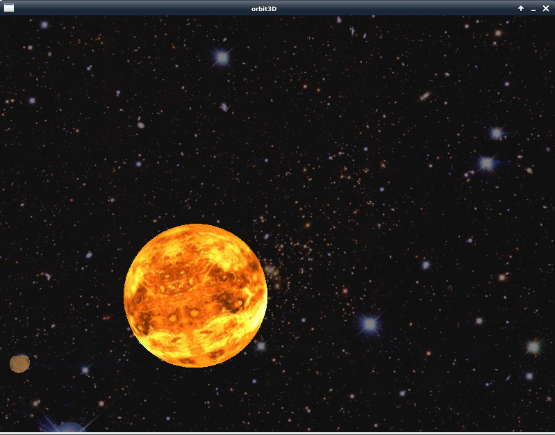
Here's a screen shot of the finished product...
And that is all there is to say, this time around, but while I am on the OpenGL subject in this blog, here is another good OpenGL set of tutorials and lessons. JAVA, maybe, but the idea is still the same where OpenGL is concerned...

OpenGL Tutorials and Lessons.

Monday 19 December 2011

OpenGL / Allegro 5.1 gluSphere()

Another snippet to document for posterity. I have been very busy working the last few days, but try to keep my hand in whenever I can. Here's what I tried.

#include "allegro5/allegro.h" 
#include "allegro5/allegro_opengl.h"

#include "allegro5/allegro_image.h"

#include "GL/glu.h"


const int SCREEN_X = 800;
const int SCREEN_Y = 600;

int main(int argc, char *argv[])
{
ALLEGRO_DISPLAY *display = NULL;
ALLEGRO_BITMAP *bmp_earth = NULL;
GLuint tex_bmp = 0;

al_init();
al_init_image_addon();

al_set_new_display_flags(ALLEGRO_OPENGL);
display = al_create_display(SCREEN_X, SCREEN_Y);
bmp_earth = al_load_bitmap("dry_world.jpg");
tex_bmp = al_get_opengl_texture(bmp_earth);

GLUquadricObj *gl_quad_obj;
gl_quad_obj=gluNewQuadric();

glMatrixMode(GL_PROJECTION);
glLoadIdentity();
gluPerspective(35.0f, (GLdouble)SCREEN_X / (GLdouble)SCREEN_Y, 1.0f, 200.0f);
glRotatef(23.0f, 0.0f,0.0f, 1.0f); // Trick photography; rotate the camera...

glMatrixMode(GL_MODELVIEW);
glLoadIdentity();

glTranslatef(0.0f,0.0f,-20.0f);
glRotatef(-90.0f, 1.0f, 0.0f, 0.0f);

//glClear(GL_COLOR_BUFFER_BIT | GL_DEPTH_BUFFER_BIT);

glEnable(GL_DEPTH_TEST);
glEnable(GL_TEXTURE_2D);
glBindTexture(GL_TEXTURE_2D, tex_bmp);

//gluQuadricNormals(gl_quad_obj, GLU_SMOOTH
);
gluQuadricTexture(gl_quad_obj, GL_TRUE);
gluSphere(gl_quad_obj,5.0f,32,32);

glDisable(GL_DEPTH_TEST);
glDisable(GL_TEXTURE_2D);

al_flip_display();
al_rest(5.0);

glDeleteTextures(1, &tex_bmp);
gluDeleteQuadric(gl_quad_obj);
al_destroy_display(display);
al_destroy_bitmap(bmp_earth);
return 0;
}

Short and sweet. I had some curiosity about using the glu extension for something other than gluPerspective(), and as I had a hankering to make a planet, I experimented with gluSphere(). Turns out it works okay with Allegro 5.1. The above is pretty minimalistic, just enough to get results.

Here's the map I used, from Celestia...
In this one, it became pretty important to enable the GL_DEPTH_TEST. Otherwise, you WILL get some funny effects. Note also, in the above code, the demo of how to rotate the camera!

Of course, gluSphere() this is not the only gluQuadricObject that OpenGL can do. Again, the main reference OpenGL Manual. Scroll the index on the left to glu, and there you have it; lots of cool stuff.

Friday 16 December 2011

OpenGL / Allegro 5.1 Alpha Transparency Experiment

Very short post this time. I stumbled around and took some shots in the dark to get Allegro 5.1's al_convert_mask_to_alpha() function to work with OpenGL. Strangely, the cookie crumbled correctly. I used a modified version of the code on my previous post, and "doctored" the image of the godesses as such...

It now has a pink background of RGB components (255, 0, 255). That pink area will be turned into an alpha channel so that it can be transparent. Next, in the code, I added the following line into main (pale grey code implies code that was not changed from the previously posted code, slightly modified code is darker grey, and the newly added code is black)...

al_set_new_display_flags(ALLEGRO_OPENGL);
display = al_create_display(SCREEN_X, SCREEN_Y);
tex_bmp = al_load_bitmap("texture2.png");
al_convert_mask_to_alpha(tex_bmp, al_map_rgb(255, 0, 255));
event_queue = al_create_event_queue();
timer = al_create_timer(1.0f/FPS);
ogl_tex = al_get_opengl_texture(tex_bmp);

The added line is taking the loaded bitmap and, using al_convert_mask_to_alpha() function with an al_map_rgb() value of (255, 0, 255), making any part of the image that is this color, technically, transparent.

Now, how to make OpenGL use that channel as transparency? Somewhere, before entering the while() loop of the application, place this snippet of code...

glAlphaFunc(GL_GREATER, 0.5);
glEnable(GL_ALPHA_TEST);


I put it just after the calls to...

al_start_timer(timer); 
setup_3D_camera();


Now, what do they do? Still a bit of a mystery to me, as yet. Here is the page where I got the idea, for future reference...

Let There Be Texture

And here are the respective OpenGL reference pages to that GL function...

glAlphaFunc()

...to scratch my head over in the following days. And as usual, glEnable() is full of useful stuff.

Anyway, here's the result (a bit tacky around the edges as a result of png anti-aliasing), but passable...


That's all, this time...

Wednesday 14 December 2011

OpenGL / Allegro 5.1 Animation and Back Face Culling

So, in this post I might say that I am now ready to tackle a slightly more complex integration of OpenGL into Allegro 5.1; Animation.


Much the same stuff that has been in my previous posts, up to a point; include the Allegro and GLU headers, set up a camera, draw a flat board with a texture on it, etcetera...

/* Comment --- reference library link line 
`pkg-config --libs allegro-5.1 allegro_image-5.1`

-lGL

-lGLU
*/


#include "allegro5/allegro.h"
#include "allegro5/allegro_image.h"
#include "allegro5/allegro_opengl.h"
#include "GL/glu.h"


const int SCREEN_X = 800;
const int SCREEN_Y = 600;
const float FPS = 60.0;

// Function to keep angle values between 0 and 359
void angle_max(GLfloat &_angle)
{
if(_angle >= 360.0)
_angle -= 360.0;
else if(_angle < 0.0)
_angle += 360.0;
}

// Function to set up camera
void setup_3D_camera()
{
glMatrixMode(GL_PROJECTION);
glLoadIdentity();
gluPerspective(35.0, GLdouble(SCREEN_X) / GLdouble(SCREEN_Y), 1.0, 100.0);
}
Except that now instead of drawing the camera straight into int main() function, I have the camera setting up in its own custom function. I also added a function called angle_max(), that receives a reference pointer of an angle. Here is a brief break down.

//DEMO EXAMPLE
const int SCREEN_X = 800;
const int SCREEN_Y = 600;
These are just the display size, in integers, to create an 800 x 600 pixel window. It may seem pretty obvoius, but I mention it here for one reason alone, one which I have not mentioned before. Allegro creates displays using integers values with al_create_display(). OpenGL uses the values of the display width and height to get the aspect ratio of the screen for the gluPerspective() function, but requires the aspect ratio to be in a double type. These integers need to be type cast to double in the gluPerspective() function, or you get some funny perspective effects when the program runs. It caught me out. That's all!

// DEMO EXAMPLE
const float FPS = 60.0;


60 frames per second. Allegro stuff. This will be the speed of the timer to draw my animation. It is just declared here.

// DEMO EXAMPLE
void angle_max(GLfloat &_angle)
{
if(_angle >= 360.0f)
_angle -= 360.0f;
else if(_angle < 0.0f)
_angle += 360.0f;
}
Very simple, and needed only to keep the angle inside the 0º to 360º constraints. OpenGL uses angles in degrees. This function accepts an angle and makes sure that it never exceeds 359.99º or falls below 0º. It is a generic angle "corrector", and any angle of float type in degrees can be passed to it for the check, simplifying the code.

The void setup_3D_camera() function is simply what has been seen in other posts on this blog, only here it is in a function. Big deal. In the end it only gets called once, anyway, to set up the glMatrixMode(GL_PROJECTION).

Now the function to draw the board, also in its own custom function this time around...

// Function to draw the 3D bill board
void draw_board(GLuint _tex, GLfloat _ang_y)
{
glMatrixMode(GL_MODELVIEW),
glLoadIdentity();

glTranslatef(0.0f, 0.0f, -20.0f);

glRotatef(0.0f, 1.0f, 0.0f, 0.0f);
glRotatef(_ang_y, 0.0f, 1.0f, 0.0f); // Y axis, _ang_y variable used here.
glRotatef(0.0f, 0.0f, 0.0f, 1.0f);

glEnable(GL_TEXTURE_2D);
//glEnable(GL_CULL_FACE);
glBindTexture(GL_TEXTURE_2D, _tex);

glBegin(GL_QUADS);

glTexCoord2f(0.0f, 0.0f);
glVertex3f(-2.5f, -2.5f, 0.0f); //lower lh corner
glTexCoord2f(1.0f, 0.0f);
glVertex3f(2.5f, -2.5f, 0.0f); //lower rh corner
glTexCoord2f(1.0f, 1.0f);
glVertex3f(2.5f, 2.5f, 0.0f); //upper rh corner
glTexCoord2f(0.0f, 1.0f);
glVertex3f(-2.5f, 2.5f, 0.0f); //upper lh corner

glEnd();

//glDisable(GL_CULL_FACE);
glDisable(GL_TEXTURE_2D);
}


Apart from the drawing of the bill board here being in a function, there are only two new and notable features. First, note that a variable for an angle is passed to this funtion (GLfloat _ang_y), and is used in the glRotatef() call for the Y axis. The implicatin is that every time the function is called, a new value of the Y axis angle may be passed to the function. That would give me an "animation" of a sorts, right?

The other feature of note is the inclusion of glEnable(GL_CULL_FACE), though commented out for now. There will be more on this face culling business at the end of the post. Just for now, related to this topic, note that the bill board has been drawn in a counter-clockwise sense; that is, I started at the bottom left vertex, went to the bottom right, up to the top right, then to the top left. The order in which the vertices are drawn is important, when it comes to face culling.

int main(int argc, char *argv[])
{
ALLEGRO_DISPLAY *display = NULL;
ALLEGRO_BITMAP *tex_bmp = NULL;
ALLEGRO_EVENT_QUEUE *event_queue = NULL;
ALLEGRO_TIMER *timer = NULL;

bool loop = true;
bool draw = false;

GLfloat angle_y = 0.0f;
GLfloat rate_y = 1.0f;
GLuint ogl_tex = 0;

al_init(); // Again, avoiding error trapping for clarity...
al_init_image_addon();

al_set_new_display_flags(ALLEGRO_OPENGL);
display = al_create_display(SCREEN_X, SCREEN_Y);
tex_bmp = al_load_bitmap("texture1.jpg");
ogl_tex = al_get_opengl_texture(tex_bmp);

event_queue = al_create_event_queue();
timer = al_create_timer(1.0f/FPS);

al_register_event_source(event_queue, al_get_display_event_source(display));
al_register_event_source(event_queue, al_get_timer_event_source(timer));

al_start_timer(timer);
setup_3D_camera();

//glCullFace(GL_BACK);
//glCullFace(GL_FRONT);

So, what's new as from the previous posts? For starters I have declared an ALLEGRO_EVENT_QUEUE and an ALLEGRO_TIMER. There are also two booleans, loop and draw. Finally, there are two new GLfloats (angle_y and rate_y). Taken from the top...

The ALLEGRO_EVENT_QUEUE is created with al_create_event_queue(), and it will be used to store events from different sources of input into the program (such as the display, or the timer, keyboard, mouse, and so on). However, in order for the event_queue to receive input from a ny of these sources, an "avenue" of communication must be opened from the source to the event_queue by using al_register_event_source(), or the program simply will not know that an input was intended at all. I register inputs for the event_queue from the display using al_get_display_event_source() and from the timer using al_get_timer_event_source(). It makes the program keep an "eye open" for events from these two sources.

The ALLEGRO_TIMER is created with al_create_timer(1.0f/FPS). Basically (remembering that FPS = 60.0), I am dividing 1 second into 60 parts. This will create a timer that will throw an ALLEGRO_TIMER_EVENT into the event_queue every 1/60 of a second. In the code (later) I can retrieve and use that timer event to control the flow of the "animation".

All of what is covered in the last two paragraphs is not specifically for OpenGL integration; it is plain old Allegro, and can be used in any Allegro 5 program. More on it at these two links.

Allegro 5 events tutorial

Allegro 5 timer tutorial

The GLfloat angle_y variable is the angle that will be passed to the custom draw_board() function, in order to set the angle of the board around its Y axis. The GLfloat rate_y is the amount by which the angle will change each frame loop of the animation.

I then start the timer with al_start_timer(timer). With this, the timer is now running and throwing ALLEGRO_EVENT_TIMER every 1/60 of a second. And finally, I call the setup_3D_camera() function.

I will ignore the two two commented out glCullFace() lines for now.

By the way, here is the bitmap I used for this sample program (an Anime "Oh! My Goddess" wallpaper cropped and "gimped")...


Now the loop that will detect the events and handle them...

 // Start the loop
while(loop)
{
ALLEGRO_EVENT event;
al_wait_for_event(event_queue, &event);
// Detect the events
switch(event.type)
{
case ALLEGRO_EVENT_DISPLAY_CLOSE:
loop = false;
break;

case ALLEGRO_EVENT_TIMER:
draw = true;
break;
}

// Draw the screen if draw = true
if(draw == true && al_event_queue_is_empty(event_queue))
{
angle_y += rate_y;
angle_max(angle_y);
al_clear_to_color(al_map_rgb_f(0.0f, 0.0f, 0.5f));
draw_board(ogl_tex, angle_y);
al_flip_display();
draw = false;
}
}


Yeah, while the boolean loop variable is true, the loop will keep cycling. First, I will make an empty ALLEGRO_EVENT structure variable, and then wait for an event to be dropped into the event_queue with al_wait_for_event(). When an event occurs, I can examine it in the event structure using a switch control loop.

If I get an ALLEGRO_EVENT_DISPLAY_CLOSE event (ie; I click on the window "X" icon to close it), I set the loop variable to false, and the program exits the loop on the next while() cycle.

If I get an ALLEGRO_EVENT_TIMER, and I will 1/60 of a second just so long as the timer is running, I set the draw variable to true. This will cause the drawing to take place by executing the if(draw == true...) statement.

When the loop variable is set to false, the while(loop) exits and the following block is performed. The application ends.

 // Clean up and kill the application
al_destroy_bitmap(tex_bmp);
al_stop_timer(timer);
al_destroy_timer(timer);
al_flush_event_queue(event_queue);
al_destroy_event_queue(event_queue);
al_destroy_display(display);
return 0;
}


Now, what about that back face culling business? If the blocks of code above (barring, of course, the //DEMO EXAMPLE blocks) are strung together and compiled, I get an animation of the goddesses spinning around on a bill board. Both sides of the bill board will be seen, the second one being a reverse image of the first. The face that shows the black haired goddess with the red shawl (Skuld, by name, incidentally) on the left is the front face, with the vertices arranged counter clockwise. If that board it flipped around around (as the animation does) the vertices will no longer be in a counter clockwise orientation. This is the back face, with Skuld on the right. All very well, but maybe I only want the front face to be visible. In this case, I un-comment the lines in the draw_board() function;

...
//glEnable(GL_CULL_FACE);
...
//glDisable(GL_CULL_FACE);
...


By default, OpenGL culls (or suppresses the drawing of) the backface, that one with clockwise vertices. If I run the program now, we will only see the face of the board that has Skuld on the left. However, we can manipulate OpenGL very easily so that it culls only the front face and leaves the back face alone. If I find the following line, just after al_start_timer()...

//glCullFace(GL_FRONT);

...and un-comment it, then recompile and run, I will only see the face that has Skuld on the right (ie; the back face).

Back face culling is useful to speed up a program that has many objects in it, which the back faces need not be drawn (for example, they are the inside of a space ship that the user will never see anyway. Some more neat tricks with back face culling here...

Video Tutorials Rock Back face Culling

That's all for this post.

Sunday 4 December 2011

OpenGL / Allegro 5.1 2D bitmap overlay panel

And here's another small tidbit of using OpenGL with Allegro 5.1. Sooner or later, rendering 3D objects is not going to be enough to interact with an application. We are going to need a 2D "control panel", which will have indicators and switches, etcetera, like this very lame one I threw together...

It is a straight forward PNG bitmap, 800 x 197 pixels. The object is to put this "panel" at the bottom of my OpenGL display, after I have rendered my "3D" object.

First some familiar stuff, except this time I'll make a flat triangle as my object just to vary a little...

Note: Once again, all the following blocks of code can be put together to create the working sample program.

#include "allegro5/allegro.h"
#include "allegro5/allegro_opengl.h"
#include "allegro5/allegro_image.h"
#include "GL/glu.h"

int main()
{
ALLEGRO_DISPLAY *display = NULL;
ALLEGRO_BITMAP *bmp_panel = NULL;

al_init();
al_init_image_addon();

al_set_new_display_flags(ALLEGRO_OPENGL);
display = al_create_display(800, 600);

bmp_panel = al_load_bitmap("panel.png");

glMatrixMode(GL_PROJECTION);
glLoadIdentity();
gluPerspective(35.0, GLdouble(800.0 / 600.0), 1.0, 200.0);

glMatrixMode(GL_MODELVIEW);
glLoadIdentity();
glTranslatef(0.0, 0.75, -10.0);

glBegin(GL_TRIANGLES);

glColor3f(0.7, 0.0, 0.1);
glVertex3f(-1.5, -1.5, 0.0);
glColor3f(0.3, 0.0, 0.3);
glVertex3f(1.5, -1.5, 0.0);
glColor3f(0.2, 0.0, 0.7);
glVertex3f(0.0, 1.5, 0.0);

glEnd();

Nothing really new here, but if I tried to put my panel onto the screen right now with al_draw_bitmap(), I would not get any results at all, as I would be trying to draw a 2D panel "into" a 3D world. OpenGL does not know how to fit it. However, there is a way. The display projection needs to be reset to 2D. This is where glOrtho() comes in handy. The following bit of code will make the OpenGL display 2D "compatible".
glMatrixMode (GL_PROJECTION);
glLoadIdentity ();
glOrtho (0.0, 800.0, 600.0, 0.0, 0.0, 1.0);

More about 2D drawing with OpenGL here...

Now I am able to draw my bitmap onto the screen with al_draw_bitmap(). Note, I use al_get_bitmap_height() to obtain how many pixels high the panel is, then subtract that value from the display Y value to place it properly on the display...
int bmp_height = al_get_bitmap_height(bmp_panel);
al_draw_bitmap(bmp_panel, 0.0, 600.0 - float(bmp_height), 0);

al_flip_display();
al_rest(5.0);

al_destroy_bitmap(bmp_panel);
al_destroy_display(display);

return 0;
}

And that would be it. Here's the result...

OpenGL / Allegro 5.1 MipMaps

With thanks to Tomasu on #allegro IRC for the help with this...

Here's how to enable mipmaps for OpenGL programs using Allegro 5.1.

In the previous post, I applied a texture to a "board" on OpenGL utilizing the allegro function al_load_bitmap(), followed by al_get_opengl_texture(). However, that texture was simply an applied bitmap. If I tried using one of the mipmap options for glTexParameterf(), such as;

glTexParameterf(GL_TEXTURE_2D, GL_TEXTURE_MIN_FILTER, GL_NEAREST_MIPMAP_NEAREST);


...the texture would not be mapped at all onto the board (it would be plain white). The solution is in making the bitmap a mipmap before using it as an OpenGL texture using al_set_new_bitmap_flags(). This must be called prior to loading the bitmap, in order for Allegro to generate the mipmaps. I opted for this as an experiment...

al_set_new_bitmap_flags(ALLEGRO_MIPMAP | ALLEGRO_MIN_LINEAR);
bmp = al_load_bitmap("texture.jpg"); // 256 x 256 pixels
ogl_tex = al_get_opengl_texture(bmp);

Then, when I called glTextParameterf() for setting the the GL_TEXTURE_MIN_FILTER and GL_TEXTURE_MAG_FILTER, I did it this way...
glTexParameterf(GL_TEXTURE_2D, GL_TEXTURE_MIN_FILTER, GL_LINEAR_MIPMAP_LINEAR);
glTexParameterf(GL_TEXTURE_2D, GL_TEXTURE_MAG_FILTER, GL_LINEAR);

The result is now a mipmap texture on the board. Pretty cool. When done loading bitmaps as mipmaps, the bitmap loading can be reset to default by resetting the flags, as such...
al_set_new_bitmap_flags(ALLEGRO_CONVERT_BITMAP);

That's the default, and any loading of subsequent bitmaps will no longer be mipmaps. The complete listing that can be used to test this function is in my previous post on this blog.

Thursday 1 December 2011

Open GL / Allegro 5.1 Basics: Textures

So, after a year, I decided to tackle OpenGL again to find that I have forgotten almost everything about it. Previously, I had used glut and explored the possibility, with some limited success, of using Allegro 4's OpenGL functionality. However, now there is a new version of Allegro; 5.1.0. These posts are going to be about using OpenGL with that particular programming API, on Linux (Debian Wheezy), with the Code::Blocks IDE.

Here are some links...

Video Tutorials Rock
Allegro Tutorial
OpenGL Reference (2.1)
OpenGL Reference (1.1)
Code::Blocks
Allegro.cc (find out more about Allegro API here...)

I believe the support for the version of OpenGL on my Linux (libgl1-mesa-dev and libglu-mesa-dev) is for version 2.1, complete. In any case, here's the pertinent output of my versions from glxinfo run in a Linux terminal (that goes with the binary NVIDIA-Linux driver for my on board GPU)....
direct rendering: Yes
client glx vendor string: NVIDIA Corporation
client glx version string: 1.4
...
OpenGL vendor string: NVIDIA Corporation
OpenGL renderer string: GeForce 7025 / nForce 630a/PCI/SSE2
OpenGL version string: 2.1.2 NVIDIA 290.10
OpenGL shading language version string: 1.20 NVIDIA via Cg compiler

With all that in mind, here we go...

The objective here is simply render a texture on a GL_QUAD-rilateral. But first it will be necessary to initialize Allegro, and make it acceptable for working with OpenGL. This is relatively easy...

(Note: The following blocks of code are completely contiguous. They can be pasted together in the order that they appear to create the complete, working listing, unless a particular block excludes itself specifically with a CAPITALIZED comment saying //DEMO EXAMPLE. Such commented blocks need not or should not be placed in the listing).

#include "allegro5/allegro.h"
#include "allegro5/allegro_opengl.h"
#include "allegro5/allegro_image.h"
#include "GL/glu.h"


int main()
{
ALLEGRO_DISPLAY *display = NULL;
ALLEGRO_BITMAP *bmp = NULL;

GLuint ogl_tex; // The OpenGL texture id.

al_init();
al_init_image_addon();

al_set_new_display_flags(ALLEGRO_OPENGL);
display = al_create_display(1200, 800);

// Load a bitmap to use as a texture
bmp = al_load_bitmap("texture.jpg"); // 256 x 256 pixels
ogl_tex = al_get_opengl_texture(bmp);

...and here is the "texture.jpg" I am using, by the way. It is some screen background I got off the web and "Gimped" down to 256 x 256.
 

So, what's important here? Several things, straight off the bat, which are going to be useful, if not indispensable, for using OpenGL with Allegro 5.1.0. In the include headers lines is "allegro_opengl.h", required to use OpenGL with the API. Also, there are the "allegro_image.h" and "glu.h" headers. The image addon is initiated in the code with the line al_init_image_addon(), and will be needed for handling the loading of the jpg image that will be used as the texture. The glu.h is needed for for using the gluPerspective() function, which will provide the camera for my OpenGL world.

The respective libraries are linked the following way, for Allegro-5.1.0;
`pkg-config --libs allegro-5.1 allegro_image-5.1`
-lGL
-lGLU
Now, before creating the ALLEGRO_DISPLAY, the call to al_set_new_display_flags(ALLEGRO_OPENGL) is, apparently, required. That said, I have tried running OpenGL through Allegro-5.1.0 excluding this call, and it works perfectly well and without any notable difference, which is strange(?).

Finally, that little block of code loads texture.jpg as an ALLEGRO_BITMAP with al_load_bitmap(), and then assigns that bitmap as a (type) GLuint texture id (ogl_tex) with al_get_opengl_texture(). It is now usable as an OpenGL texture for later on.

Onwards...
glMatrixMode(GL_PROJECTION);
glLoadIdentity();
gluPerspective(35.0, 1200.0 / 800.0, 1.0, 400.0);

This is the camera view on the OpenGL world.

glMatrixMode(GL_PROJECTION) puts OpenGL in the mode that allows the definition of the view camera. glLoadIdentity() then pr oceeds to enable, or execute that mode, replacing any glMatrixMode that may have been in use before. Finally, gluPerspective() sets up the qualities of the camera. In order, the first parameter sets the angle, in degrees that the camera sees. With it, you can simulate a telephoto lens (with low FOV angles), or fish eye lenses (with wide FOV angles). The second parameter is the aspect ratio of the view port, or display. It is obtained by dividing the display width by the display height, (1200 / 800) in this case. The last two parameters are the closest render distance and farthest render distance, respectively, in OpenGL units. Anything closer than 1.0 or farther than 400.0 units from the Camera will not be rendered. Yeah, okay. I understand all the above better worded that way! And that's the camera done.

The next bit of code builds the object (a flat board!) that we are going to see, and applies the texture we prepared earlier...
al_clear_to_color(al_map_rgb(0,0,50));

glMatrixMode(GL_MODELVIEW);
glLoadIdentity();

glTranslatef(2.0f, -1.5f, -18.0f);
glRotatef(75.0, -1.0f, 0.0f, 0.0f);
glRotatef(10.0, 0.0f, -1.0f, 0.0f);
glRotatef(0.0, 0.0f, 0.0f, 1.0f);

glEnable(GL_TEXTURE_2D);
glBindTexture(GL_TEXTURE_2D, ogl_tex);

glTexParameterf(GL_TEXTURE_2D, GL_TEXTURE_MIN_FILTER, GL_LINEAR);
glTexParameterf(GL_TEXTURE_2D, GL_TEXTURE_MAG_FILTER, GL_LINEAR);
glTexParameterf(GL_TEXTURE_2D, GL_TEXTURE_WRAP_S, GL_MIRRORED_REPEAT);
glTexParameterf(GL_TEXTURE_2D, GL_TEXTURE_WRAP_T, GL_REPEAT);

// Other options for GL_TEXTURE_WRAP_S and GL_TEXTURE_WRAP_T...
// GL_CLAMP, GL_CLAMP_TO_BORDER, GL_CLAMP_TO_EDGE, GL_MIRRORED_REPEAT, GL_REPEAT

glBegin(GL_QUADS);

glTexCoord2f(0.0, 0.0); // Bottom left hand corner
glVertex3f(-3.5, -6.5, 0.0); // X,Y,Z
glTexCoord2f(6.0, 0.0); // Bottom right hand corner
glVertex3f(3.5, -6.5, 0.0); // X,Y,Z
glTexCoord2f(6.0, 8.0); // Top right hand corner
glVertex3f(3.5, 6.5, 0.0); // X,Y,Z
glTexCoord2f(0.0, 8.0); // Top left hand corner
glVertex3f(-3.5, 6.5, 0.0); // X,Y,Z

glEnd();

glDisable(GL_TEXTURE_2D);

Okay, that looks quite long and confusing right now, but it is not the end of the world. I will dissect it...

al_clear_to_color() is self explanatory, really. The only reason I mention it is to show that it is perfectly compatible with OpenGL.

And again, we use glMatrixMode() and glLoadIdentity(), though this time we set the GL_MODELVIEW mode, as we are going to make a flat quadrilateral (that is, a GL_QUAD).

glTranslatef(X,Y,Z) needs a very quick review. It moves the "origin" (let's say) of our object to be created to a point in 3D space, defined by X,Y,Z, in OpenGL units. In this case, I moved the origin +2.0 X (to the right), -1.5 Y (down) and -18.0 Z (into the screen). Basically, it is a matrix translate, as the name implies.

glRotatef(angle, X,Y,Z) is a matrix rotate , around the origin. Here I break the rotation process up into three separate operations, one for each axis, with it's own angular change. To put it simply, positive rotation values rotate the object around it's origin counter-clockwise, as viewed parallel from the positive side of local object's local axis it is being rotated around.

We now come to the texture handling part. The first thing to do is to enable the texture with glEnable(GL_TEXTURE_2D). There's a hell of a lot of things that can be "enabled" with this function in OpenGL. Here, suffice to say that our texture(s) are enabled so that we can use them on our object, okay? The function has an opposite number, glDisable(), which is used to "disable" just about everything that can be enabled, as the program situations require, and is described on the same reference page as glEnable(). Note that at the end of the code block above, I disable GL_TEXTURE_2D, after I have used it.

Following that, I invoked glBindTexture(GL_TEXTURE_2D, ogl_tex). As "bind" suggests, this function "attaches" or "associates" (but does not specifically "place" or "position") the texture, referenced by its GLui nt identifier, to the object we are about to build. Enough said about that, really. Let's get onto setting that texture and making the object...

It's time to look at setting some parameters for that texture. For this, I use glTexParameterf() or glTexParameteri(). GL_TEXTURE_MAG_FILTER and GL_TEXTURE_MIN_FILTER basically define how the texture image is "compressed" or "spread" onto the object when the rendered siz e of the object is not equal to the true size of the texture bitmap. This will occur most of the time. Right here, I set both of them as GL_LINEAR, as I am not doing any mip-mapping just yet.

glTexParameter can also be used to set the "tiling" (wrapping) behavior characteristics of the texture on the object. GL_TEXTURE_WRAP_S determines how the texture will behave horizontally across the object, if it is repeated more than once, that is. More on how that is done in a minute. I want the texture to repeat itself mirroring itself every time it is rendered horizontally, so I use GL_MIRRORED_REPEAT.

GL_TEXTURE_WRAP_T determines how the texture will repeat vertically. Here I just want it to repeat and be a non-mirrored replica of itself, so I use GL_REPEAT.

In all cases above the target (the first parameter of glTexParameter) was my 2D texture, that is GL_TEXTURE_2D.

At last, I can get down to making my object. Fir st I will tell it what, exactly, I am planning to build, so that OpenGL has an idea of how many vertices will be involved. I emp loy glBegin(GL_QUADS) for this. A quadrilateral, with four vertices.

Now, I could just go ahead and make a QUAD with the following;
// DEMO EXAMPLE
glVertex3f(-3.5, -6.5, 0.0); // X,Y,Z bottom left
glVertex3f(3.5, -6.5, 0.0); // X,Y,Z bottom right
glVertex3f(3.5, 6.5, 0.0); // X,Y,Z top right
glVertex3f(-3.5, 6.5, 0.0); // X,Y,Z top left

...which is fairly self explanatory, but I will have wasted all that effort in setting up the texture.

I will "place", or "position" if you like, the texture on my QUAD by using glTexCoord2f(). Now that reference description I found a bit overly complicated for the present purposes. It would suffice here to say that these are more or less the same thing as u/v coords, as used in 3D modeling programs. In this case, take a look at the picture of the texture up above in this post. The lower left corner is (X,Y) position (0,0), the lower right (1,0), the top right (1,1) and the top left (0,1). The function glTexCoord2f() uses these coords to map the 2D texture onto the object, as many times as we want, abiding by the repeat properties set with the GL_TEXTURE_WRAP parameter. glTexCoord2f() is specified just before creating the respective vertex point with glVertex3f().

The following example would map the texture exactly onto the QUAD once;
// DEMO EXAMPLE
// Bottom left
glTexCoord2f(0.0, 0.0);
glVertex3f(-3.5, -6.5, 0.0);

// Bottom right
glTexCoord2f(1.0, 0.0);
glVertex3f(3.5, -6.5, 0.0);

// Top right
glTexCoord2f(1.0, 1.0);
glVertex3f(3.5, 6.5, 0.0);

// Top left
glTexCoord2f(0.0, 1.0);
glVertex3f(-3.5, 6.5, 0.0);
...and this would map it 2 times horizontally and once vertically...
// DEMO EXAMPLE
// Bottom left
glTexCoord2f(0.0, 0.0);
glVertex3f(-3.5, -6.5, 0.0);

// Bottom right
glTexCoord2f(2.0, 0.0);
glVertex3f(3.5, -6.5, 0.0);

// Top right
glTexCoord2f(2.0, 1.0);
glVertex3f(3.5, 6.5, 0.0);

// Top left
glTexCoord2f(0.0, 1.0);
glVertex3f(-3.5, 6.5, 0.0);
Once I have finished drawing my QUAD and placing the texture as I want it, I end the drawing with glEnd(), and disable work on the texture with glDisable(GL_TEXTURE_2D). Then it is just a case of flipping the buffer to the display, letting the image show for a few seconds, and cleaning up...
al_flip_display();
al_rest(10.0);

glDeleteTextures(1, &ogl_tex);
al_destroy_bitmap(bmp);
al_destroy_display(display);
return 0;
}

That would be it. You would get something like this...


More coming soon...

Obtaining Normals of a 3D vector

Before I address any 3D stuff in this blog I am going to review the process of obtaining normalized 3D vectors. It is not difficult, but with my penchant to forget everything in five minutes, I consign it to posterity in this post. Below are 3 distances (X, Y, Z) of a 3D vector. The object is to normalize each of them as if the total length (of a 3D hypotenuse) were one;

(X, Y, Z)

(5.4, 3.7, 6.2)

Obtain the true total length...

sqrt(5.4² + 3.7² + 6.2²) = 9.0161

Now simply divide each component by the total length...

5.4 / 9.0161 = 0.5989 (for X)

3.7 / 9.0161 = 0.4104 (for Y)

6.2 / 9.0161 = 0.6877 (for Z)

So our vector, normalized to one, now looks like;

(0.5989, 0.4104, 0.6877)

And that is it, basically.

Wednesday 30 November 2011

Code Box Test

Just found this which might help writing blocks of code in my posts...

Let's see;

#include "allegro5/allegro.h"
#include "allegro5/allegro_opengl.h"
#include "allegro5/allegro_image.h"
#include "GL/glu.h"


int main()
{
ALLEGRO_DISPLAY *display = NULL;
ALLEGRO_BITMAP *bmp = NULL;

GLuint ogl_tex; // The OpenGL texture id.

al_init();
al_init_image_addon();

al_set_new_display_flags(ALLEGRO_OPENGL);
display = al_create_display(800, 600);

// Load a bitmap to use as a texture
bmp = al_load_bitmap("texture.jpg"); // 256 x 256 pixels
ogl_tex = al_get_opengl_texture(bmp);

glMatrixMode(GL_PROJECTION);
glLoadIdentity();
gluPerspective(35.0, 800.0 / 600.0, 1.0, 400.0);

glClear(GL_COLOR_BUFFER_BIT | GL_DEPTH_BUFFER_BIT);

glMatrixMode(GL_MODELVIEW);
glLoadIdentity();
glTranslatef(0.0f, 0.0f, -15.0f);

glEnable(GL_DEPTH_TEST);

glEnable(GL_TEXTURE_2D);
glBindTexture(GL_TEXTURE_2D, ogl_tex);

glTexParameteri(GL_TEXTURE_2D, GL_TEXTURE_WRAP_S, GL_REPEAT);
glTexParameteri(GL_TEXTURE_2D, GL_TEXTURE_WRAP_T, GL_REPEAT);

glBegin(GL_QUADS);

glNormal3f(0.0, 0.0, 1.0);

glTexCoord2f(0.0, 0.0); // Bottom left hand corner
glVertex3f(-1.5, -1.5, 0.0); // X,Y,Z
glTexCoord2f(2.0, 0.0); // Bottom right hand corner
glVertex3f(1.5, -1.5, 0.0); // X,Y,Z
glTexCoord2f(2.0, 2.0); // Top right hand corner
glVertex3f(1.5, 1.5, 0.0); // X,Y,Z
glTexCoord2f(0.0, 2.0); // Top left hand corner
glVertex3f(-1.5, 1.5, 0.0); // X,Y,Z

glEnd();

glDisable(GL_TEXTURE_2D);
glDisable(GL_DEPTH_TEST);

al_flip_display();

al_rest(10.0);

glDeleteTextures(1, &ogl_tex);
al_destroy_bitmap(bmp);
al_destroy_display(display);
return 0;
}


How does that look?

Yeah, not too bad. I am learning something about blogging, after all. I'll use that from now on. The font size is 80%.

<"<">

As for the listing in the test example, well, that will be the subject of my next series of posts here.

Sunday 2 October 2011

Increasing the time resolution

Okay, I said I would conclude the installments on the naval gun, but as it is now familiar, I will use it here (once more) to introduce time update resolution problems. Yeah, I lied! Imagine that...

In the naval gun example, the time update was at X1. Because gravity and velocity is "rated", let's say, on a "once per second" basis, I elected to do the update of the shell "state" once every second. This is all very well for a demo, but let's say I want to include the naval gun in a real time "HMS Exeter in The Java Sea" type of game. If I left the screen update at 1 second, it would be a very "chuggy" game indeed, a bit like the old days when over ambitious simulators were made to run on 286's.

So, here's a simple example of a ballistic model;

while(y_pos >= 0) // while the shell is above the sea
{
x_vel = cos(angle) * vel;
y_vel = sin(angle) * vel;

angle = atan2f((y_vel - grav), x_vel);
vel = sqrtf((pow((y_vel - grav), 2) + pow(x_vel, 2)));

x_pos += x_vel;
y_pos += (y_vel - grav);

usleep(1000000);
}


This updates every second (usleep(1000000)), with a second based physics model. But I want it to update, say, 4 times every second! Here's what I do;

double FPS = 4;
// Could be an int, but it is better to stay compatible with the types it will be used with.
useconds_t t_factor = useconds_t(1000000 / FPS);

while(y_pos >= 0) // while the shell is above the sea
{

x_vel = cos(angle) * vel;
y_vel = sin(angle) * vel;

angle = atan2f((y_vel - (grav / FPS)), x_vel);
vel = sqrtf((pow((y_vel - (grav / FPS)), 2) + pow(x_vel, 2)));

x_pos += (x_vel / FPS);
y_pos += ((y_vel / FPS) - (grav / FPS));


usleep(t_factor);

}

What I have to consider here is that gravity is only going to be doing a quarter of its work (as it is 9.807 m/s²). Also, velocity is going to need to go only a quarter of the distance (m/s) per update. However, the velocity itself should not really be played with until it is turned into its components (read on).

It is also important to consider that the gravity "reduction" needs to be included in the angle recalculation. If it is not, the the rate of change stays as if on a one second basis, and considerably shortens the range (as the angle would be changing at X4 of what it should). Finally, the usleep function is modified by the t_factor, making the real screen update run at 4 times a second, so a real time simulation is retained.

Where drag is concerned, the force of drag would need to be quartered (drag / FPS), and this would be subtracted from the "real" momentum (velocity * mass). That is why it is important not to affect the net velocity by FPS (ie; do NOT turn an 800 m/s velocity into a 200 m/s to simplify the calculations), and to modify the computed components instead, when they are being added to the positions.

Dang! I wish I had been able to see that BBC program on Exeter!

Saturday 1 October 2011

Link to Naval Gun

So, that concludes the installments of the naval gun. Likely I will continue to develop it a bit more. The continuing story of it now goes over to my Sourceforge account. Free for all, source and configuration files.

Wednesday 28 September 2011

Final polish to the Naval Gun

And now I want to study that interpolation function, so I have reference to return to in case I forget (again) how I did it. What happens?

double ref_Mach_table[MACH_CD_ELEMENTS] =
{-0.10, 0.00, 0.40, 0.60, 0.87, 1.02, 1.15, 2.40, 3.40};

double ref_Cd_table[MACH_CD_ELEMENTS] =
{0.000, 0.231, 0.229, 0.172, 0.139, 0.333, 0.341, 0.268, 0.255};

//............

double Cd_Calculator(double Mach)
{
int index_count;

for(index_count = 0; index_count < MACH_CD_ELEMENTS; index_count++)
{
if(ref_Mach_table[index_count] > Mach)
break;
}

double inter_factor =
(Mach - ref_Mach_table[index_count - 1]) / (ref_Mach_table[index_count] - ref_Mach_table[index_count - 1]);

double output =
((ref_Cd_table[index_count] - ref_Cd_table[index_count - 1]) * inter_factor) + ref_Cd_table[index_count - 1];

return output;
}


The function is called using the calculated Mach number as the parameter. The for loop counts up (increasing the index_count) until the value in the Mach table (the ref_Mach_table array element of the index_count) exceeds the value of the passed Mach number, then breaks out with the corresponding index_count.

The range of the table values, the upper and the lower, that enclose the passed Mach value is then calculated;

ref_Mach_table[index_count] - ref_Mach_table[index_count - 1]

For example, a value of Mach 1.9 is passed. That being between 2.40 and 1.15, the formula will calculate the Mach range of;

2.40 - 1.15 = 1.25

Then the difference of the passed Mach value from the lower table value is calculated;

1.9 - 1.15 = 0.75

Then, in coefficient (percentage, if you like) of the relation of the relation of the true difference to the available table range is calculated;

0.75 / 1.25 = 0.6

And that is the interpolation factor for the ref_Cd_table array, and what is happening in the line that calculates inter_factor. I am just doing a straight forward linear interpolation here, by the way. Armed with inter_factor and index count, I then move to the ref_Cd_table and find the range of the two Cd values that correspond to the index_count and index_count - 1.

ref_Cd_table[index_count] - ref_Cd_table[index_count - 1]

These values are 0.268 and 0.341. So we get;

0.268 - 0.341 = -0.073

A negative value, as the Cd is reducing with increase in Mach at these velocities. I multiply that by the inter_factor to get what the Cd change is between the two Cd table values at 0.6 (60%) between them.

0.6 x -0.073 = -0.0438

I now add that to the Cd value that corresponds to the [index_count - 1] element, which is 0.341;

0.341 + -0.0438 = 0.2972

And that is the new interpolated Cd returned by the function (result of the computations for the variable output). This is the Cd value that gets passed to the drag calculation formula.

Now, finally, a refinement of the drag calculations by obtaining the air density at the shell's altitude. As air density reduces with increasing altitude, the shell is going to be traveling through a less dense medium at the top of its trajectory. I believe it was this ship, that ended her days as a war trophy and was subjected to nuclear bomb tests at Kwajalein atoll, that had high elevation guns (37º, where most maximum elevations were in the region of 25º to 30º), which greatly enhanced the fighting capabilities of the already formidable 8" main weapon by sending the shell high into the lower density atmosphere.

I got the density ratios for ISA out of a book I have, Aerodynamics for Naval Aviators, though I am sure it can be found also with a good internet search.

const int REF_RHO_ELEMENTS = 12;

double ref_rhos[REF_RHO_ELEMENTS] =
{1.000, 0.8617, 0.7385, 0.6292, 0.5328, 0.4481, 0.3741, 0.3099, 0.2462, 0.1936, 0.1522, 0.1197};

// These are percentage values of the air density, relative to the SL density of 1.225 kg/m³
// The resolution of the density ratio is for every 1525 meters.

// Related declarations...
double rho_gradient = 1525; // Meters
double actual_rho;

double Rho_Calculator(double altitude, double gradient, double sl_rho)
{
double alt_ref = altitude / gradient;
// Eg; 1872 / 1525 = 1.227541

int index_count = int(alt_ref);
// Eg; int(1.227541) = 1. This is the index position in ref_rhos[]
// As this is a constant increment of altitude gradient,
// the interpolation factor is pretty direct, as in;

double inter_factor = alt_ref - index_count;

double rho_coeff =
((ref_rhos[index_count + 1] - ref_rhos[index_count]) * inter_factor) + ref_rhos[index_count];

return sl_rho * rho_coeff;
}


This is actually a simpler interpolation than the previous, as it does not have a variable primary interpolation range, as the first one did. The altitude increments are constant, and only the density ratio lapse relaxes with increasing altitude. It is fairly self explanatory. It is called, BEFORE the drag calculation, like this...

actual_rho = Rho_Calculator(ypos, rho_gradient, ISA_Rho);

And the drag calculation, to recap, looks like this...

double Velocity_Calculator(double vel, double mass, double rho, double d_coeff, double FA)
{
double energy = vel * mass;
double drag = 0.5 * rho * pow(vel, 2) * d_coeff * FA;
energy -= drag;
return energy / mass;
}


Note that I now have it as a separate function, called from inside the update loop, after all the Rho and Mach calculations are done, like this...

velocity =
Velocity_Calculator(velocity, mass_kg, actual_rho, Cd, frontal_area);


That would be all, for now.

Monday 26 September 2011

More for the Naval Gun

As the title says, a bit more for the Naval Gun. I am going to do this in a couple of posts, to keep it in bite sized portions. Ballistics, especially of a spinning shell, is a complex, 3 dimensional arena. This model is limited to 2D for the moment. The day may come when I decide to tackle precession induced drift. For the moment, I just want to make this one, as it is, a bit more credible. One of the features of a naval shell, as fired from those magnificent warships of World War I and II, was that they were supersonic, a while before aircraft broke the legendary "sound barrier".

One of the notable traits of approaching "the speed of sound" is that the behavior of drag changes. There is a sharp increase in drag through the transonic region, and then a gradual fall off of this increased drag as the body accelerates beyond the speed of sound. This behavior is best represented, in a simulator model, by making the Coefficient of Drag a variable, the value of which is dependent upon the shell's velocity in relation to Mach 1. In my previous model, Cd was a fixed value. This was okay for starters, but it is NOT correct.

Now, things get a bit more intricate. The speed of sound is itself dependent on the atmospheric temperature. If you are a pilot, or even a dedicated "simmer", you will probably have an ARC-1 or E6B Flight Computer. There is a little scale on the computer side, where you match up a temperature to an M symbol, and read off the speed of an equivalent Mach number from the inner scale to knots on the outer scale. As a rough guide, a velocity of 340.278 m/s is equivalent to Mach 1 at 15º C (International Standard Atmosphere at Sea Level). And every drop of 1º C incurs a reduction of Mach 1 equivalent velocity by 0.61 m/s, approximately. So, if the temperature is 12º C, then Mach 1 is equivalent to;

340.278 - ((15 - 12) * 0.61)

To get the Mach number from this, divide the actual velocity of the shell (in m/s) by the corresponding Mach 1, in m/s, obtained for the given temperature.

Mach_Number_of_Shell = Velocity_of_Shell_ms / Velocity_of_Mach_1_ms

And that, basically, is what I am going to do with my model as a required step in determining a variable Coefficient of Drag. The temperature drops at an environmental lapse rate of 1º C per every 152.39 meters gained.

Declarations first, with all the others;

double ISA_temp_C = 15;
double temp_meters_degree_C = 152.39; // Meters of altitude per every -1º C
double ref_Mach_1 = 340.278; // Meters per second at 15º C
double Mach_fall_off = 0.61; // Mach meters per second less per every -1º C
double velocity_Mach;

Now, I decided to make a small function that I would call from inside the update loop. Here it is;

double Mach_Calculator(double altitude, double SL_temp, double alt_temp_lapse, double ref_M1, double Mach_lapse, double vel)
{
double temp_at_alt = SL_temp - (altitude / alt_temp_lapse);
double Mach_1_at_alt = ref_M1 - ((SL_temp - temp_at_alt) * Mach_lapse);
return vel / Mach_1_at_alt;
}

And that was it, in the simplest terms. I now have the shell velocity expressed in Mach number. I call the function with these parameters;

velocity_Mach =
Mach_Calculator(ypos, ISA_temp_C, temp_meters_degree_C, ref_Mach_1, Mach_fall_off, velocity);


Onwards. Now let's go get that variable Coefficient of Drag. There are (very complicated) ways of computing Cd. I opted for an easy way out, at this stage. Check out this page. Down on the Doppler Radar-measurements section, there is a model of a bullet's coefficient of drag at different Mach velocities. I mapped something like that into two arrays, declared globally, in my program, like this;

const int MACH_CD_ELEMENTS = 9;

double ref_Mach_table[MACH_CD_ELEMENTS] =
{-0.10, 0.00, 0.40, 0.60, 0.87, 1.02, 1.15, 2.40, 3.40};

double ref_Cd_table[MACH_CD_ELEMENTS] =
{0.000, 0.231, 0.229, 0.172, 0.139, 0.333, 0.341, 0.268, 0.255};


Simply matched up some Mach numbers (first array) to some Cd values (second array. Now it will just be a case of using the computed Mach velocity of the shell to find a corresponding Cd. So, it is all very well to say, looking at the two arrays, that if the shell is traveling at Mach 1.15, then the Cd is 0.341 (both being the seventh element in their respective arrays), but what if the shell is doing Mach 1.95? The Cd value is somewhere between 0.341 and 0.268. We need to interpolate. Here's the function that does it...

double Cd_Calculator(double Mach)
{
int index_count;

for(index_count = 0; index_count < MACH_CD_ELEMENTS; index_count++)

{
if(ref_Mach_table[index_count] > Mach)
break;
}

double inter_factor =
(Mach - ref_Mach_table[index_count - 1]) / (ref_Mach_table[index_count] - ref_Mach_table[index_count - 1]);


double output =
((ref_Cd_table[index_count] - ref_Cd_table[index_count - 1]) * inter_factor) + ref_Cd_table[index_count - 1];


return output;

}

So, what's it doing? That's the subject of the next post, where I will also interpolate to get a variable atmospheric density at different altitudes, adding a bit more polish to the model. For the moment, this function gets called AFTER determining the Mach number and BEFORE calculating the drag (in the update loop), like this...

Cd = Cd_Calculator(velocity_Mach);

That's already improved the model. It now has a variable Coefficient of Drag, dependent on the Mach number, which is in turn dependent on the shell velocity at different air temperatures.

Friday 23 September 2011

Naval Gun

And now a brief intermission from all that "space stuff". I thought I might tackle the challenge of modeling a ballistic trajectory of a 15" naval gun, as used on this ship, for example. Now there are a couple of factors that influence the trajectory of a projectile of a given velocity; gravity and drag.

Gravity I have already looked into in my previous posts. For this model, fired in a local area on the surface of the Earth, the variations in its acceleration would be negligible, so I established it constant at 9.807 m/s². At this point I will just go ahead and plot a trajectory without drag (air resistance) to see what I get.

Apart from the gravity, I established some initial data for the calculation. They would be shell velocity (initial, or muzzle velocity if you like), and angle (elevation) of the gun, so that it fires upwards like a mortar shot, the way it did, and loft the shell off towards its target in the distance. Here's how the program started off (I am not going to do that complete color formatting anymore, it is a pain. From now, comments are going to be pale blue, code in dark blue);

int main()
{
// variable declarations...
double grav_accel = 9.807;

double velocity = 785; // meters per second
double xpos = 0, ypos = 0; // The shell positions, each unit a meter.
double xvel, yvel; // The shell X and Y (2D) velocity components.
double angle = 0.40; // Angle in radians, approximately 23º.
// For the record (I am always mixing this up)....
// To convert radians to degrees, first divide them by PI, then multiply by 180.
// To convert degrees to radians, first divide them by 180, then multiply by PI.

// Code continues after the following comment....

Once that is established, we can set up a loop to move the shell. The thing to consider here is that during the upward travel of the shell, gravity is going to slow its velocity on the Y component (vertical). This will slowly alter the trajectory, as it will also slow its total velocity. And on the "way down" gravity will increase the projectile velocity (drag being nonexistent, to start with. Later we will see how drag affects this).

This is what needs to be calculated.

// Code continues here...

while(ypos >= 0) // While the shell is above the "ground", or "sea", as it were.
{
xvel = cos(angle) * velocity;
yvel = sin(angle) * velocity;

xpos += xvel;
ypos += (yvel - grav_accel);

velocity = sqrt(pow(xvel, 2) + pow((yvel - grav_accel), 2));
angle = atan2f((yvel - grav_accel), xvel);

usleep(1000000);
}
return 0;
}

At first glance it may appear that there is a bit much there. Why not just compute the vertical velocity component and leave it at that? There would be no change to the horizontal component of the velocity as it changed its trajectory, which is what really happens. That is why. As the shell travels upwards, a component of gravity is subtracting velocity from the shell's total velocity.

For example, if the code were left simply as...

xvel = cos(angle) * velocity;
yvel = sin(angle) * velocity;

xpos += xvel;
ypos += (yvel - grav_accel);


...and looped through as that, the horizontal velocity would always be the result of Cos(angle) x velocity (ie; Cos(22º) x 785 = 727.8 m/s). This would extend the range of the gun unrealistically, as there would be no degradation of its velocity caused by it "fighting its way uphill" at the beginning of its trajectory. The new velocity is calculated by invoking Pythagoras with the new components of X and Y velocity. Then the new angle of the resultant trajectory is also calculated from the new components (atan()), and that data is fed back into the loop. The program will run as it is, now.

However, that is not the end of the story. The shell travels through the atmosphere, and the atmosphere has a density that causes aerodynamic drag. The formula for drag is;

Drag = 0.5 x Velocity² x Air_Density x Drag_Coefficient x Frontal_Area

In SI units, that would give you the force of drag in Newtons (I believe. Most of my usage of lift and drag formula in the past have been in Imperial units, which provides the force in pounds. This is the first time I am applying it with SI units). So, now I needed to supply some more data to the program in order to calculate this. Velocity we already have, so we add to the variable declarations the following;

double frontal_area = 0.1148; // m², about the frontal area of a 15 inch diameter shell.
double Cd = 0.22; // An estimated, "probable" coefficient of drag.

double Rho = 1.225;
// kg/m³, air density, according to SL ISA.

double drag;


All very well, but now the drag has to "work" against something. That "something" would be the momentum (inertia) of a shell of a certain mass traveling at a certain velocity. Here is where I get a bit "plauged" by doubt, but I do believe that I am correct in stating that the motion inertia of the shell is equivalent to its mass multiplied by its velocity. Let's call it "momentum" for the moment, to differentiate it from kinetic energy, which is a different formula (and provides preposterously large results for the purpose of this model). The unit of the product would be the Kg Meter per Second (Newton Second). I add these two more variables to the declarations in the code;

double mass = 870; // kg
double momentum;


And now to the calculations. This would go inside the loop, in the code above, just after the angle calculation and before the usleep() function call.

drag = 0.5 * Rho * pow(velocity, 2) * Cd * frontal_area;
momentum = (velocity * mass) - drag; // I believe the units are compatible here.
// At least, the results of the running program are quite acceptable.

velocity = momentum / mass;
// From the energy, devise the new velocity, and then loop back
to the beginning,
// armed with the new trajectory angle and shell velocity.

It might not be perfect, but the output (which can be seen by adding some cout statements to the code) is actually quite convincing. There is a slight excess of range, but I believe it might be because the Cd is a tad low. After all, it was only estimated. The shell goes up almost 4 km, travels 29 km, taking 55 seconds to do so, and arrives at the target at a velocity of about 480 m/s, having decelerated from its original 785 m/s, and been at about 540 m/s at the top of the trajectory. These figures are not far off the performance of the real gun.

After note:
I had some fun with this one. Obviously, the code can be cleaned up, or neatly packaged away in a function, but the basic idea is there. A couple of members of a naval history forum provided me with some additional sources of information (data) on gun ranges and trajectories. I really was not far off, at all, except that it is closer to the real performance of the gun if the coefficient of drag is raised to 0.25 or 0.26, instead of 0.22.

'Till the next installment!